









A laser rangefinder can transmit a clean pulse and still miss the measurement if its receiver cannot separate a weak return from noise. That makes the detector important, but a detector specification by itself does not tell you whether the complete ranging system will work.
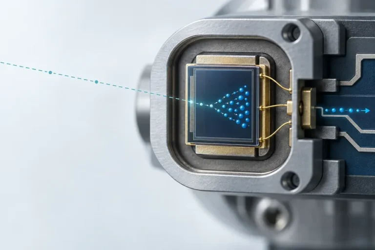
Ein avalanche photodiode rangefinder uses an APD in the optical receiver to convert returned light into electrical current and multiply that current internally. The added gain can lift weak echoes above downstream electronic noise, but it also introduces excess noise, high-bias requirements, temperature sensitivity, and recovery constraints that must be designed into the full receiver.
How an avalanche photodiode rangefinder uses internal gain
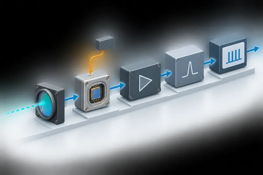
In a pulsed rangefinder, the receive optics collect a small fraction of the light scattered back from the target. An optical filter rejects out-of-band background light, and the detector converts the remaining photons into charge. The receiver electronics then amplify and qualify the electrical pulse before a timing circuit estimates the interval between transmission and reception.
The APD changes the first electrical step. A photon absorbed in the device creates an electron-hole pair. Under a strong reverse electric field, a carrier can gain enough energy to create additional carriers through impact ionization. Repeated multiplication produces an electrical signal larger than the original primary photocurrent.
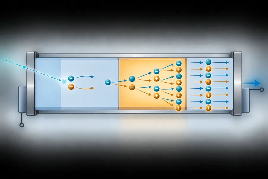
This is linear-mode avalanche gain, not the complete ranging calculation. The APD does not know the target distance. It supplies an electrical representation of the return; the transimpedance amplifier, filtering, threshold or constant-fraction stage, time-to-digital circuitry, and firmware determine whether the return is accepted and how its timing becomes a distance estimate. Our guide to direct and indirect time-of-flight methods explains why the downstream signal path differs with the ranging architecture.
Avalanche gain helps only when the receiver uses it well
Internal gain is valuable because it occurs before most downstream electronic noise is added. If the primary photocurrent is below the useful input range of the amplifier, moderate avalanche multiplication can improve the receiver signal-to-noise ratio.
More gain is not automatically better. Avalanche multiplication is statistical, so it adds excess noise. The multiplication process also takes time, while detector area, junction capacitance, packaging parasitics, and the TIA input influence bandwidth and pulse shape. At high return levels, the detector or amplifier can compress or saturate, delaying recovery before the next usable echo.
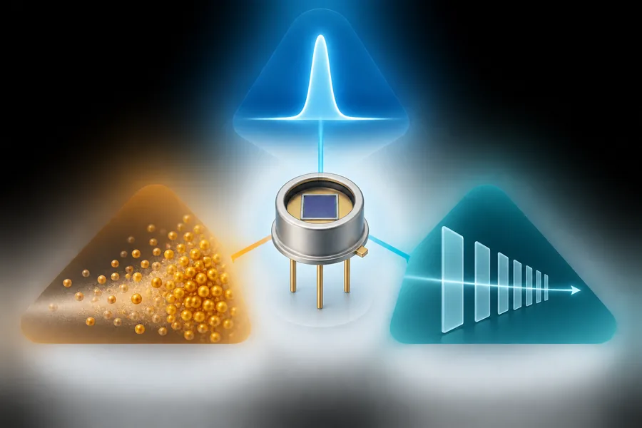
The practical target is therefore an operating point for the complete receiver, not the highest number in an APD table. A useful design review asks whether gain lifts the weakest specified return above the electronics noise floor while preserving the timing bandwidth, linear region, and recovery needed for the application. That receiver margin is only one part of the broader link budget described in our guide to maximale Reichweite von Laser-Entfernungsmessern.
Temperature makes bias control part of the measurement chain
APD gain changes steeply with reverse bias near breakdown, and the gain at a fixed bias also changes with temperature. The correct compensation curve is device-specific. An OEM receiver may regulate detector temperature, adjust bias from a characterized temperature relationship, or combine both approaches, but it should not treat a room-temperature set point as a universal operating condition.
Bias quality matters as well. Ripple or drift on the high-voltage rail modulates gain, which can shift pulse amplitude and affect the point at which a timing discriminator fires. The detector, temperature sensor, bias generator, TIA, and timing method need to be qualified as one chain.
APD, PIN photodiode, or SPAD: choose by signal regime
These detectors solve related problems in different operating regimes. The table is a selection starting point, not a substitute for a receiver noise model and test data.
| Receiver choice | Where it is often useful | Main advantage | Main design cost |
|---|---|---|---|
| PIN photodiode | Stronger returns, shorter paths, or cost- and power-sensitive designs | Simple biasing and no avalanche excess noise | No internal multiplication before the amplifier |
| Linear-mode APD | Weak, fast analog returns where pre-amplifier gain improves the noise budget | Internal gain with pulse-amplitude information retained | High-bias control, excess noise, temperature dependence, and overload recovery |
| SPAD or array | Photon-event detection and time-correlated architectures | Very high event sensitivity | Quenching, dead time, afterpulsing, pile-up, and statistical processing |
Wavelength compatibility comes first. Silicon detectors are widely used in the visible and near-infrared region, while longer near-infrared or short-wave-infrared receivers commonly require compound-semiconductor detectors such as InGaAs. The exact responsivity, gain, noise, breakdown behavior, active area, and bandwidth still depend on the selected device; do not transfer a result from one detector structure to another.
An APD also cannot guarantee a longer measurement range by itself. Transmit energy, beam divergence, target reflectance and angle, receive aperture, optical transmission, filter bandwidth, detector response, electronic noise, ambient light, acceptance logic, and allowable output all contribute. The right question is whether the complete receiver meets the defined return envelope and test conditions.
The APD is one part of a complete receiver chain
The detector should be selected with the optics and electronics, not handed to the circuit team as an isolated part number. In an avalanche photodiode rangefinder, start with the weakest and strongest expected optical returns, the wavelength, pulse shape, ambient spectrum, operating temperature, and required measurement rate. Then allocate performance across the receive chain.
Optical path and active area
The receive aperture and focal geometry determine how much return reaches the detector. A larger active area can relax alignment tolerance, but its higher capacitance may reduce bandwidth or complicate the TIA. A spectral filter can reduce solar background, yet its angle shift, temperature behavior, and passband tolerance must remain compatible with the source wavelength and field of view.
TIA, threshold, and timing walk
The TIA converts detector current into voltage while setting a major part of receiver gain and bandwidth. Downstream limiting or variable-gain stages must handle both weak echoes and strong near returns. A simple fixed threshold can produce amplitude-dependent timing walk; the appropriate discrimination and calibration method depends on the pulse shapes and dynamic range the system must accept.
Ambient background can raise detector current and receiver noise even when the desired echo is unchanged. Filtering, baseline estimation, gain management, and decision thresholds are coupled choices. Our article on background noise and adaptive thresholds covers that system-level problem in more detail.
Recovery and measurement cadence
A receiver that detects a weak distant echo in isolation may still fail after a strong reflection from a window, housing edge, foreground object, or highly reflective target. Test recovery time, baseline restoration, and false-trigger behavior across the actual cadence. Do not verify only the single clean pulse shown on a bench oscilloscope.
Qualification questions that catch receiver problems early
Ask for conditions and methods, not just headline sensitivity. A credible detector or module review should answer these questions:
- Which detector material and structure are used, and how do their spectral response and gain match the source wavelength?
- How is operating gain defined, measured, and controlled across temperature and device variation?
- What detector area, capacitance, TIA bandwidth, and pulse-width conditions apply to the quoted receiver performance?
- How are bias ripple, dark current, background current, and excess noise included in the noise budget?
- How does the receiver recover after strong returns, and what minimum separation between return events was tested?
- Which target, ambient-light, aperture, filter, temperature, and acceptance settings apply to a detection claim?
- How are calibration data, detector lot, firmware, and receiver configuration tied to production traceability?
LUMEXIS designs and manufactures Laser-Entfernungsmessermodulen within an integrated optical, electronic, firmware, and weak-signal processing workflow. Our Wuxi engineering team and 14,000-square-meter Taizhou manufacturing base support cleanroom assembly, temperature cycling, burn-in screening, and final performance testing. That system view matters because detector gain is useful only when the optical, electrical, thermal, and algorithmic interfaces remain controlled in production.
For a new project, our laser-ranging engineering services can support selection, integration, validation, and troubleshooting from sample evaluation through production. Standard products can ship within three days; custom configurations and private-label programs follow project-specific requirements and lead times. See our Laser-Entfernungsmesslösung for the supported civil and industrial system context.
Häufig gestellte Fragen
Does an APD automatically increase laser rangefinder range?
No. An APD can improve receiver sensitivity when its internal gain usefully lifts weak photocurrent above downstream noise. Maximum range still depends on the entire optical and electrical link budget, target and atmosphere, alignment, background light, signal processing, and test method. Too much gain can add noise or reduce usable dynamic range.
Why does APD gain change with temperature?
Avalanche multiplication depends on carrier acceleration and impact ionization inside the semiconductor. Lattice scattering changes with temperature, so a fixed reverse bias does not produce constant gain across the operating range. Designers use device-specific temperature characterization, bias compensation, thermal control, or a combination of these methods.
Is an APD the same as a SPAD?
No. A conventional rangefinder APD often operates below breakdown in linear mode, where output amplitude remains related to incident light. A SPAD operates above breakdown in Geiger mode and produces a discrete avalanche event that must be quenched. The readout architecture, dead-time behavior, and processing model are different.
Should 905 nm and 1535 nm receivers use the same detector?
Usually not by assumption. Detector material, structure, spectral response, gain, noise, and breakdown behavior must match the operating wavelength. Silicon APDs are common around 905 nm, while 1535 nm systems commonly use InGaAs-family detectors. Verify the exact device data and receiver conditions rather than applying a wavelength label alone.
What information should an APD receiver supplier provide?
Request the detector type, operating gain and bias method, temperature behavior, active area and capacitance, receiver bandwidth, noise conditions, overload recovery, optical filter conditions, acceptance logic, and traceability plan. Performance claims should state the pulse, target, aperture, ambient, and temperature conditions used.
Referenzen
- Hamamatsu Photonics, Technical note: Si APD.
- Hamamatsu Photonics, A technical guide to silicon photomultipliers, Section 1.
- Analog Devices, Low-Noise APD Bias Circuit.
- Jin-Ho Lee et al., A CMOS Optoelectronic Receiver IC with an On-Chip Avalanche Photodiode for Home-Monitoring LiDAR Sensors, Sensoren, 2021.
Ready to review a receiver or module requirement? Send our applications engineers the wavelength, return-signal envelope, target conditions, timing method, operating temperature, mechanical envelope, interface, and expected volume. We can recommend a standard module or scope a custom configuration and validation plan.