
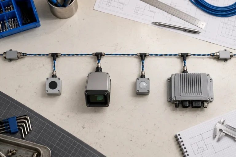
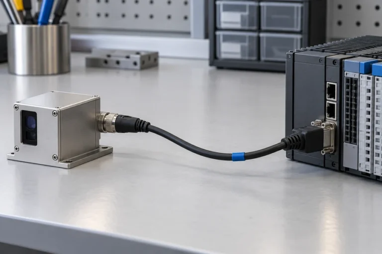
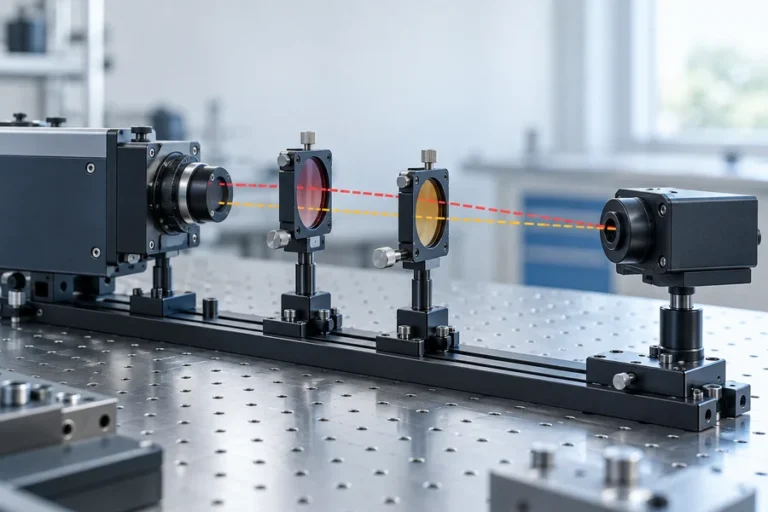
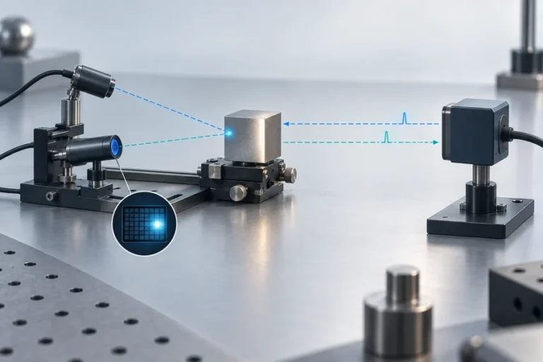

Два датчика могут использовать схожую физику измерения дальности и при этом решать разные задачи. Выбирайте по требуемой информации, а не по надписи на корпусе.
Практическое сравнение лазерного дальномера и LiDAR начинается с требуемого результата, а не с излучателя.
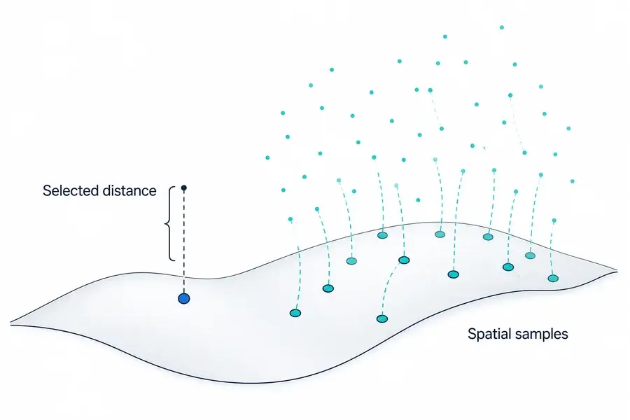
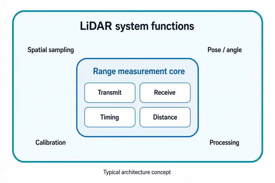
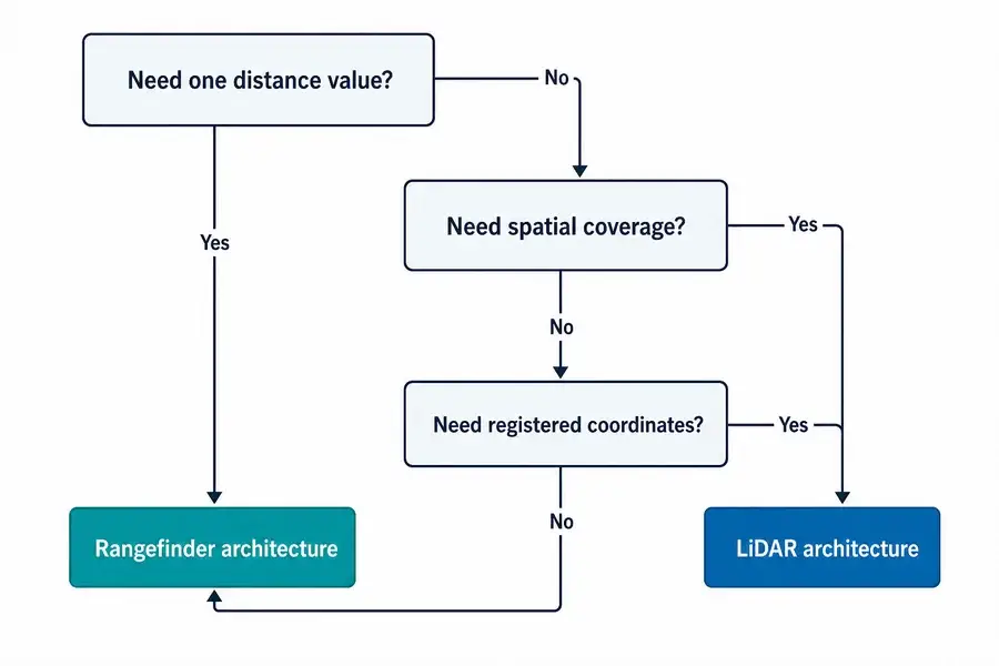
Лазерный дальномер обычно возвращает расстояние вдоль выбранной линии визирования. LiDAR собирает образцы дальности по полю и связывает их с направлением или положением, формируя профиль, карту глубины или облако точек. Дальномер может быть одной из подсистем внутри LiDAR, но управление лучом, пространственная регистрация, калибровка и обработка делают LiDAR более крупной сенсорной архитектурой.
Лазерный дальномер vs LiDAR: разница в результате
Лазерный дальномер отвечает на сфокусированный вопрос: как далеко находится выбранная цель вдоль этой оси визирования? Результатом может быть одно измерение по команде или непрерывный поток. Хост решает, что делать с этим расстоянием.
LiDAR отвечает на пространственный вопрос. Он связывает измерения с направлением, пикселем или положением платформы. Результатом может быть 2D-профиль, кадр глубины или XYZ-облако точек.
Это делает “одна точка против множества точек” полезным первым приближением, а не универсальным определением. Некоторые системы LiDAR механически управляют лучом. Другие используют твердотельное управление, матрицы детекторов, импульсную подсветку или гибридную выборку. Устойчивое различие заключается в том, выдает ли прибор выбранный поток дальностей или пространственно организованные данные дальности.
Для определения на уровне модуля см. что содержит модуль лазерного дальномера.
Они разделяют физику измерения дальности, но не границы системы
Обе категории могут передавать свет, собирать отраженный сигнал и оценивать расстояние по времени прохождения туда и обратно. Некоторые системы вместо этого используют фазовые методы. Сам метод измерения дальности не определяет, называется ли готовый прибор дальномером или LiDAR.
Типичный модуль дальномера объединяет источник, оптику, детектор и аналоговый тракт, схемы тайминга или фазы, обработку сигнала и интерфейс с хостом. Он возвращает расстояние без построения модели сцены. Наше руководство о как работает лазерное измерение дальности прослеживает эту цепочку.
Система LiDAR добавляет функции, необходимые для размещения множества образцов дальности в пространстве. В зависимости от архитектуры это могут быть управление лучом или формирующий приемник, измерение угла сканирования, синхронизация часов, входы положения и ориентации, геометрическая калибровка и обработка облака точек. Руководство NOAA по LiDAR, например, описывает объединение времени прохождения, угла сканирования и прямой геопривязки для вычисления трехмерных координат.
Именно поэтому дальномер может быть подсистемой внутри сканирующего LiDAR-инструмента. Он обеспечивает измерение дальности; остальная часть системы определяет, где этот образец принадлежит.
Когда оценивается сам источник, платформа импульсного волоконного лазера Lumexis для LiDAR охватывает другой системный уровень, чем полный сканер.
Сравните требования, которые действительно меняют конструкцию
Правильная архитектура становится яснее, когда спецификация результата написана до спецификации датчика.
| Требование | Лазерный дальномер | Система LiDAR | Последствия интеграции |
|---|---|---|---|
| Основной результат | Расстояние до выбранной цели или оси | Пространственный профиль, кадр глубины или облако точек | LiDAR требует координатной модели и модели данных |
| Покрытие | Узкое, нацеленное или механически перемещаемое хостом | Несколько направлений сцены или пикселей за цикл сбора | Схема сканирования или геометрия массива становится требованием |
| Нагрузка на хост | Относительно небольшие сообщения о расстоянии | Более крупные пространственные наборы данных | Обработка, хранение и передача должны быть спланированы |
| Знание движения | Необходимо, когда хост должен интерпретировать движущуюся линию визирования | Часто необходимо для регистрации образцов с движущейся платформы | Синхронизация времени и позы влияет на качество карты |
| Калибровка | Выверка оси, смещение дальности, проверка цели и окружающей среды | Калибровка дальности плюс угловая, пространственная, временная и часто мультисенсорная | Ответственность за калибровку должна быть определена заранее |
| Наилучшее соответствие | Известная целевая ось или ось управления | Обнаружение сцены, картографирование, реконструкция поверхности | Выбор на основе решения, которое должен принять хост |
Покрытие — это не только поле зрения. Уточните, как дискретизируется поле, как часто каждая точка посещается повторно и как сообщается о зонах с низкой достоверностью.
Система координат имеет значение, как только датчик движется. Значение дальности может быть корректным, но его отображаемая XYZ-позиция — ошибочной из-за погрешности угла, временного смещения, ошибки позы или механического изгиба. Для управления по фиксированной оси эти дополнительные источники ошибок могут отсутствовать или обрабатываться существующей геометрией машины.
Скорость передачи данных и задержка также меняют интеграцию. Пространственное зондирование может требовать декодирования пакетов, временных меток, фильтрации, регистрации, обработки достоверности и достаточных вычислительных мощностей для соблюдения сроков контура управления.
См. разницу в области применения между решением лазерной дальнометрии по выбранной цели и решением LiDAR и 3D-картографирования.
Точность, дальность, мощность и стоимость не имеют универсального победителя
Во многих сравнениях заявляется, что одна категория точнее, дальнобойнее, компактнее, дешевле или энергоэффективнее. Эти утверждения несостоятельны без общих условий.
Точность измерения расстояния дальномером напрямую не сопоставима с абсолютной XYZ-точностью карты LiDAR. Карта включает погрешность дальности плюс калибровку углов, синхронизацию, позу платформы, регистрацию и иногда компенсацию движения. И наоборот, устройство LiDAR может выполнять повторные измерения во многих направлениях, тогда как дальномер концентрирует свой оптический и вычислительный бюджет на одном выбранном пути.
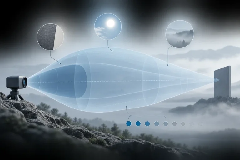
Дальность также зависит от отражательной способности цели, апертуры, расходимости, чувствительности приемника, атмосферы, фонового света, юстировки, обработки сигнала, частоты измерений и критерия приемки. Мощность и стоимость должны сравниваться при одинаковых границах системы: голый модуль и полноценный пространственный датчик — это не эквивалентные спецификации материалов.
Для вариантов архитектуры дальномеров и их компромиссов используйте руководство по типам лазерных дальномерных модулей в качестве отправной точки.
Выбирайте дальномер, когда один поток расстояний решает задачу управления
Дальномер обычно эффективен, когда цель или ось известны. Примеры включают зазоры, высоту над поверхностью, управление дистанцией, позиционирование по выбранному признаку и расстояние до инспекции.
Формулируйте требование в терминах цели, а не только максимальной дальности. Определите размер цели и диапазон отражательной способности, угловую неопределенность, частоту обновления, допустимую частоту недействительных показаний, рабочую среду, механический корпус, электрический интерфейс и способ валидации конечной установки.
Это сохраняет четкость области применения датчика и интерфейса хоста, избегая пространственных данных, которые контроллер отбросит.
Выбирайте LiDAR, когда пространственное покрытие является результатом
LiDAR уместен, когда система должна обнаруживать поверхности или объекты в пределах поля, а не измерять одну известную линию визирования. Гражданское картографирование, дистанционное зондирование, инспекция инфраструктуры, профилирование рельефа и 3D-реконструкция зависят от пространственного покрытия.
Команда должна определить геометрию дискретизации, полезную плотность точек, поведение повторных посещений, временные метки, системы координат, движение, калибровку, поля достоверности, формат вывода и программное обеспечение нижнего уровня. Плотное облако точек бесполезно, пока эти элементы не контролируются.
Выбор сканера следует за сценой. Статические, движущиеся, линейно-сканирующие, матричные и авиационные системы не имеют одинаковой нагрузки по калибровке. Относитесь к “LiDAR” как к началу обсуждения архитектуры, а не к его концу.
Определите интерфейс до запроса датчика
Перед запросом рекомендации отправьте краткое описание системы:
- Требуемый выход: одно расстояние, профиль, кадр глубины или облако точек.
- Цель и сцена: размер, диапазон отражательной способности, края, фоны и вероятные помехи.
- Геометрия: диапазон расстояний, поле зрения, неопределенность наведения и движение платформы.
- Синхронизация: частота обновления, задержка, синхронизация и требования к временным меткам.
- Среда: температура, фоновый свет, атмосфера, вибрация и ограничения корпуса.
- Интерфейсы: питание, связь, запуск, формат данных и диагностика.
- Механический корпус: размер, масса, крепление, окно, тепловой путь и доступ для юстировки.
- Валидация: цели, рабочие условия, метрики прохождения/непрохождения и объем выборки.
Инженеры по применению LUMEXIS могут рассмотреть эти входные данные в рамках выбора продукта, интеграции, валидации и устранения неполадок. Наша команда проектирует и производит лазерные дальномерные модули и лазерные источники LiDAR, обладая возможностями в области оптики, оптомеханики, электроники, прошивки, терморегулирования и слабосигнальной дальнометрии. Инженерная поддержка и поддержка настройки доступна для стандартных, индивидуальных и подходящих программ с частной маркировкой; стандартные продукты могут быть отгружены в течение трех дней, тогда как сроки индивидуальных проектов зависят от проекта.
Часто задаваемые вопросы
Является ли лазерный дальномер тем же самым, что и LiDAR?
Обычно нет на уровне продукта. Дальномер, как правило, возвращает расстояние вдоль выбранной линии визирования. LiDAR организует измерения в нескольких направлениях или пикселях в пространственные данные. Базовый механизм дальнометрии может быть схожим, и некоторые поставщики используют термины нестрого, поэтому оценивайте выход и границы системы, а не только название.
Можно ли использовать лазерный дальномерный модуль внутри системы LiDAR?
Да. В некоторых сканирующих архитектурах дальномер обеспечивает измерение расстояния, тогда как управление лучом, измерение угла, синхронизация, позиция/ориентация, калибровка и обработка размещают каждую выборку в профиле или облаке точек. Совместимость по-прежнему зависит от частоты обновления, запуска, интерфейсов, оптической геометрии и синхронизации.
Может ли дальномер создавать облако точек?
Сам по себе нет. Хост может перемещать или направлять дальномер и комбинировать каждое расстояние с известным углом и позой, но результирующая система добавляет пространственную дискретизацию, калибровку и обработку. На этой границе полный прибор выполняет функцию сканирования, подобную LiDAR, даже если исходный модуль возвращает расстояния.
Всегда ли LiDAR точнее лазерного дальномера?
Нет. Определите точность, которая сравнивается. Дальномер может указывать ошибку расстояния вдоль одной оси, тогда как выходные данные LiDAR могут требовать точности дальности, угла, положения, синхронизации и регистрации. Сравнивайте обе системы на одной и той же цели, расстоянии, окружающей среде, состоянии движения, частоте обновления и итоговом выходном показателе.
Использует ли каждый LiDAR движущийся сканер?
Нет. Механическое сканирование распространено, но также существуют твердотельное управление лучом, вспышечные или матричные методы захвата глубины и гибридные подходы. Общим требованием является пространственная выборка и организация множества измерений, а не один обязательный механизм управления.
Ссылки
- Центр прибрежных услуг NOAA, Lidar 101: Введение в технологию LiDAR, данные и применения.
- Геологическая служба США, Наземная технология обнаружения и определения дальности с помощью света.
- Геологическая служба США, EROS играет важную роль в эволюции технологии LiDAR и её применений.
- Leica Geosystems, Эволюция LiDAR.
Если вы сообщите тип выходного сигнала, цель, диапазон, поле зрения, движение, интерфейс, окружающую среду и габариты, свяжитесь с инженерной командой Lumexis. Мы можем помочь определить, подходит ли стандартный модуль дальномера, лазерный источник LiDAR или нестандартная конфигурация для определённых вами границ системы.