
Dos opciones de fuente de 1.5 µm para arquitecturas seleccionadas de LiDAR y detección.
Plataforma de fuentes OEM de 1535 nm y 1550 nm
Láseres de fibra pulsados para LiDAR
Lumexis desarrolla láseres de fibra pulsados de nanosegundos compactos para LiDAR, teledetección, mapeo, inspección industrial e instrumentos científicos. La gama de productos existente incluye fuentes compactas de 1535 nm y 1550 nm, láseres de fibra de alta potencia pico y una fuente de luz LiDAR de ocho canales. Las especificaciones publicadas abarcan potencia pico de 1.16 kW hasta 15 kW, repetición de 1–3000 kHz, ancho de pulso de 1–60 ns y salida óptica FC/APC, FC/UPC o fibra multimodo.
La potencia pico, la potencia media, la tasa de repetición y el ancho de pulso dependen de la configuración. Confirme la hoja de datos del modelo seleccionado antes de fijar el diseño óptico, eléctrico o térmico.
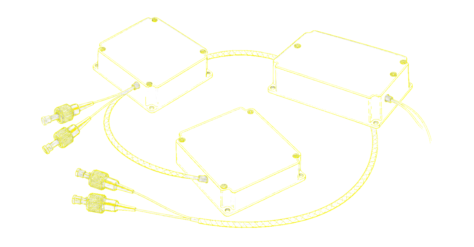
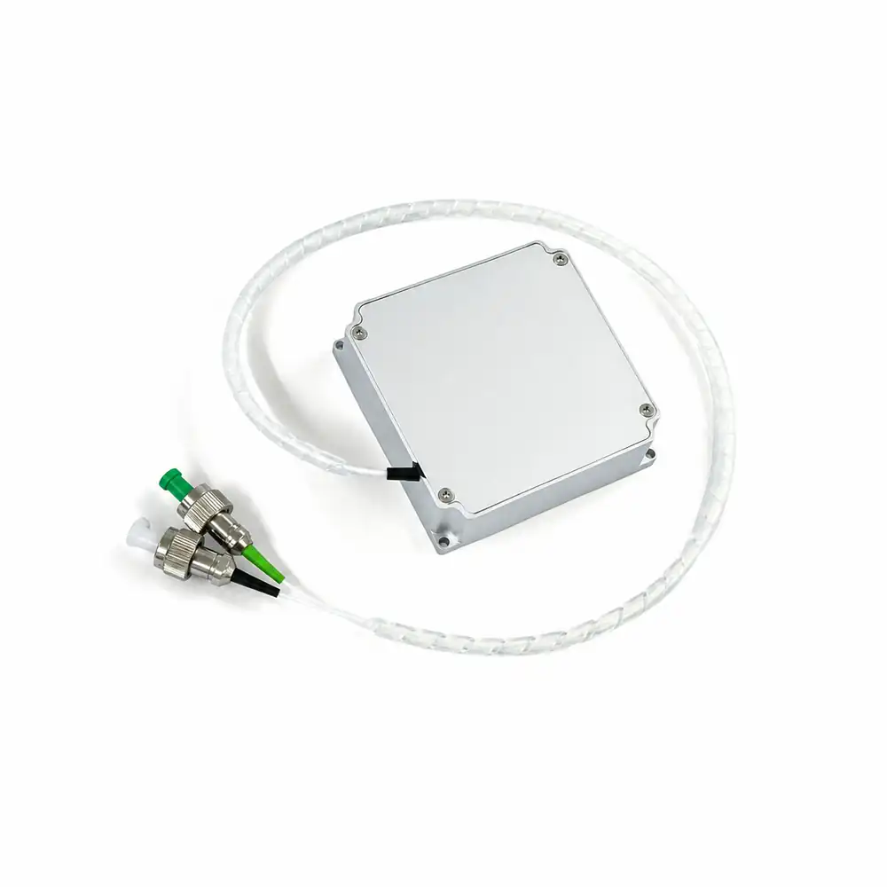 1535 nm / 1,2 kW
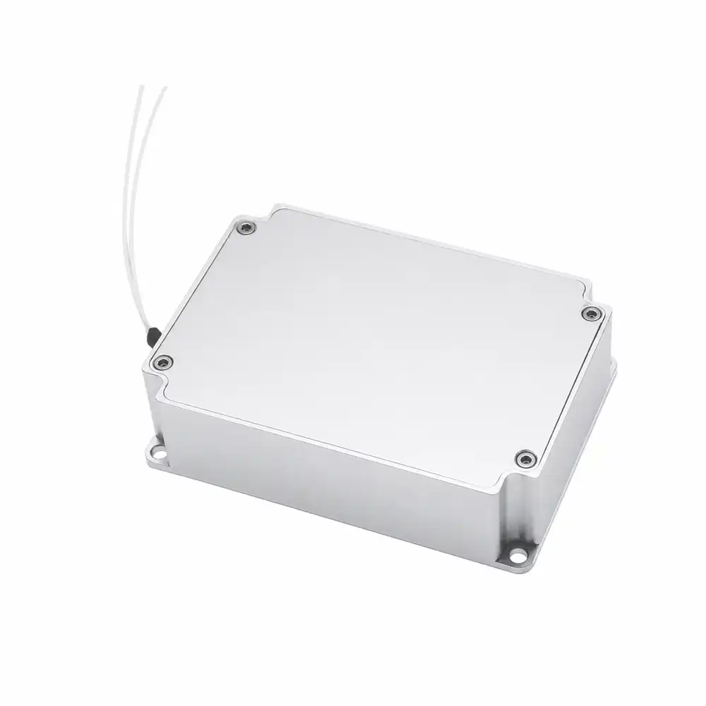 1550 nm / 1,6 kW
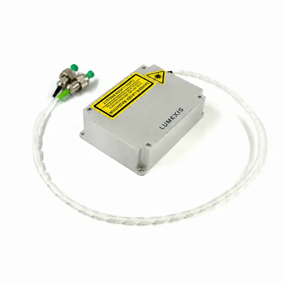 1550 nm / 3 kW
Clases de potencia pico publicadas, desde arquitecturas de fuente compactas hasta de alta potencia.
Ajustes de pulso de nanosegundos según el modelo y la configuración.
Rango de repetición publicado en el archivo de productos existente.
La opción de conector depende del modelo; verifique con la especificación seleccionada.
Rango publicado para la serie; confirme el límite térmico real del host.
Gama completa de productos
Elija la fuente según las condiciones de pulso y la arquitectura LiDAR final.
La potencia pico por sí sola no define el rendimiento del sistema. Compare longitud de onda, ancho de pulso, tasa de repetición, presupuesto de potencia media, tipo de conector e interfaces mecánicas/térmicas antes de la liberación del diseño.
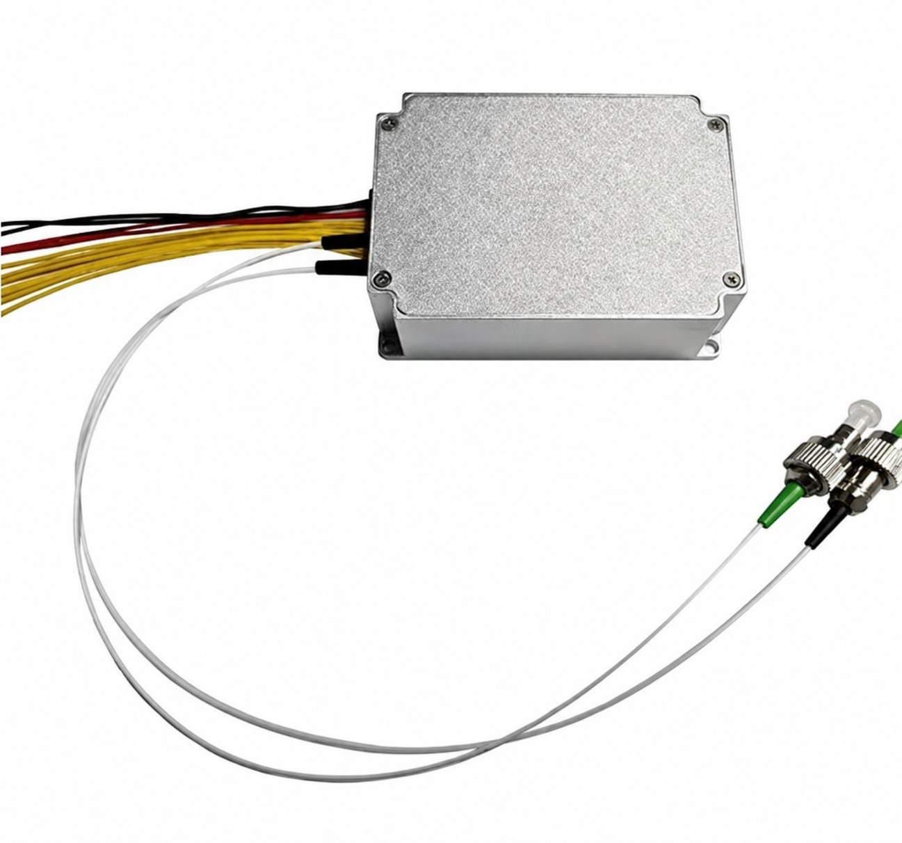
1535-LXMC1,2KW
Láser de fibra pulsado de 1.2 kW de 1535 nm
100 / 500 / 2000 kHz; 2.5 / 3 / 3.5 ns; 1.2 W de media; FC/APC + FC/UPC.
1550-LXMC1,6KW
Láser de fibra pulsado de 1.6 kW de 1550 nm
100 / 500 / 2000 kHz; 2.5 / 3 / 3.5 ns; 2.1 W de media; FC/APC.
1550-LXMC3KW
Láser de fibra pulsada de 1550nm y 3kW
50 / 500 / 2000 kHz; 3 / 3 / 5 ns; 2.0 W de media; FC/APC.
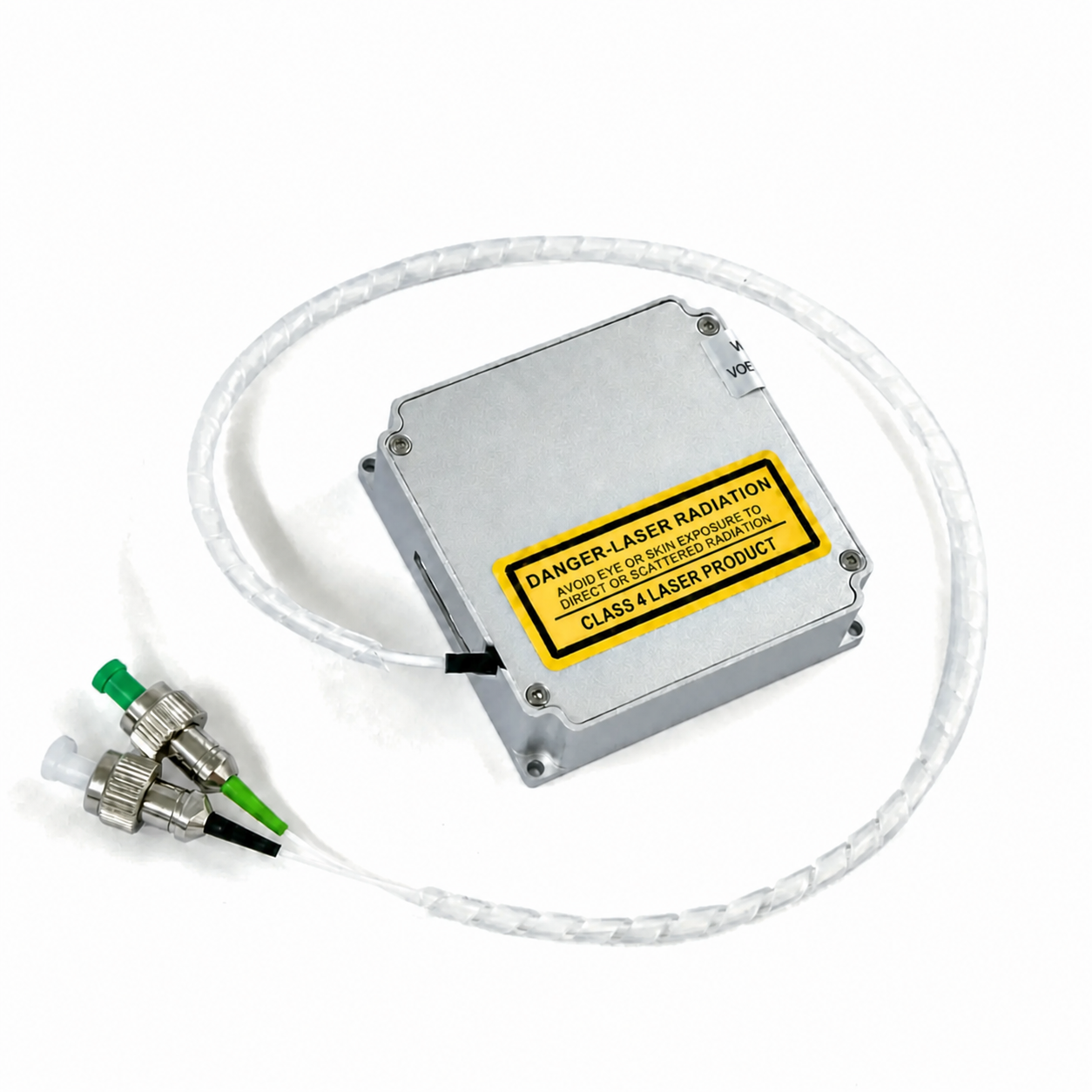
1535 NM PULSADO
Láser de fibra pulsado de 1535 nm
3 ns típico; 100–2000 kHz ajustable; 0.7–1.1 W de media; FC/APC + FC/UPC.
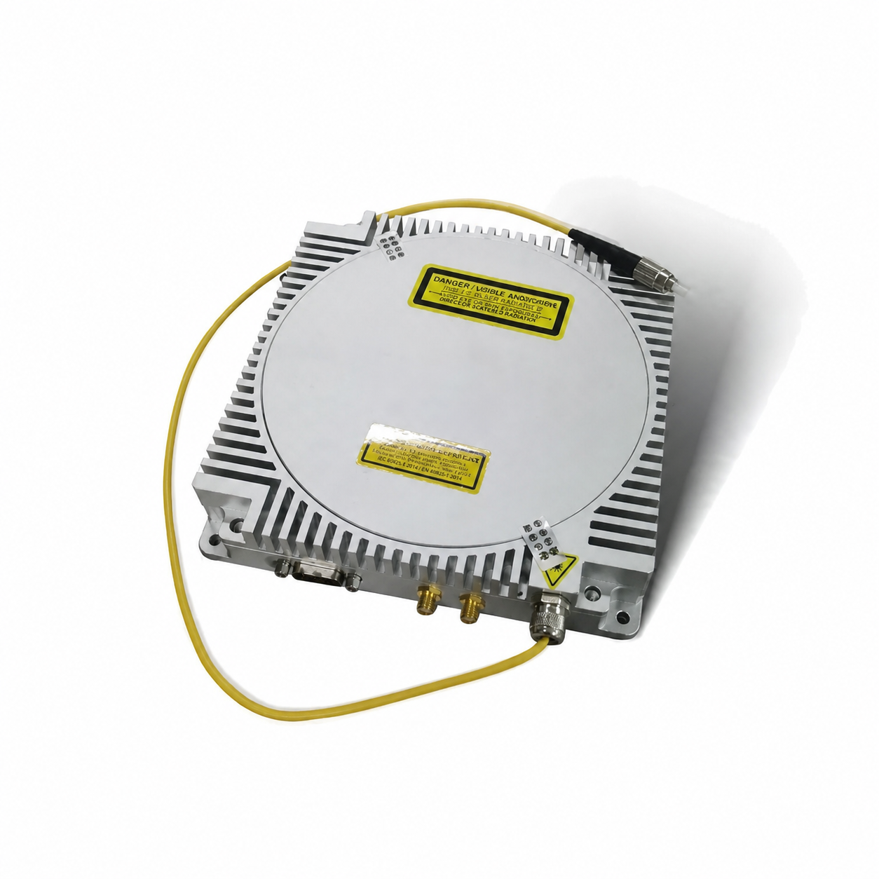
1550 ALTA POTENCIA PICO
Láser de fibra de alta potencia pico de 1550 nm
4 ns; 30–100 kHz; 3–6 W de media; salida de fibra multimodo.
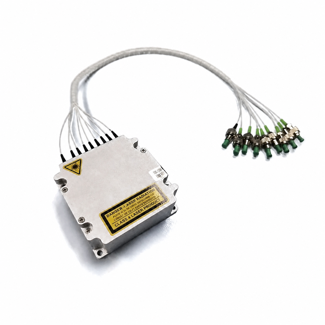
1550 8-EN-1
Fuente de luz LiDAR 8 en 1 de 1550 nm
Arquitectura de fuente multicanal integrada; tasa de repetición e interfaz revisadas según la aplicación.
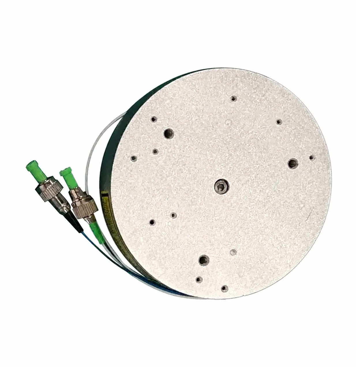
1550 ERBIO
Láser de fibra de erbio pulsado de 1550 nm
5 µJ a 100 kHz / 3 ns; 1–60 ns; 1–3000 kHz; FC/APC.
Comparación de modelos
Compare los parámetros técnicos publicados en una tabla.
Los números a continuación son los valores de selección publicados localmente. La especificación técnica específica del pedido define el punto de operación final, la interfaz y las condiciones de aceptación.
| Modelo | Longitud de onda | Potencia máxima | Ajustes de repetición | Ajustes de ancho de pulso | Potencia media | Salida óptica | Dimensiones | Temp. de funcionamiento. |
|---|---|---|---|---|---|---|---|---|
| 1535-LXMC1,2KW | 1535 nm | 2 kW | 100 / 500 / 2000 kHz | 5 / 3 / 3.5 ns | 2 W | FC/APC + FC/UPC | 55 × 55 × 16 mm | −40 a +75°C |
| 1550-LXMC1,6KW | 1550 nm | 6 kW | 100 / 500 / 2000 kHz | 5 / 3 / 3.5 ns | 1 W | FC/APC | 50 × 70 × 19 mm | −40 a +75°C |
| 1550-LXMC3KW | 1550 nm | 3 kW | 50 / 500 / 2000 kHz | 3 / 3 / 5 ns | 2,0 W | FC/APC | 50 × 70 × 19 mm | −40 a +75°C |
| 1535 nm Pulsado | 1532–1537 nm | 1160 W | 100–2000 kHz | 3 ns típico | 7–1.1 W | FC/APC + FC/UPC | 55 × 55 × 16 mm | −40 a +85°C |
| 1550 nm Compacto | 1547–1553 nm | 1–2 kW | 1–2 MHz | 1–10 ns | 95–1.05 W | FC/APC | 50 × 70 × 19 mm | −40 a +70°C |
| 1550 nm Alto pico | 1545–1555 nm | 12 kW típ.; hasta 15 kW | 30–100 kHz | 4 ns | 3–6 W | Fibra multimodo | 160 × 160 × 30 mm | −40 a +60°C |
| 1550 nm Erbio | 1545–1555 nm | 2 kW | 1–3000 kHz | 1–60 ns | 8 W | FC/APC | Ø90 × 24.5 mm | −40 a +70°C |
Nota de especificación: La alimentación es de 9 / 12 / 13 V para los tres modelos listados. Los valores de pulso y repetición representan configuraciones listadas, no una garantía de que cada combinación esté disponible. Confirme la selección con ingeniería de Lumexis.
Pulso óptico de nanosegundos
Pulso semillaAmplificador de fibraConformación de pulsoSalida de fibra
Fundamentos del láser de fibra pulsada
Del pulso semilla a la salida LiDAR entregada por fibra.
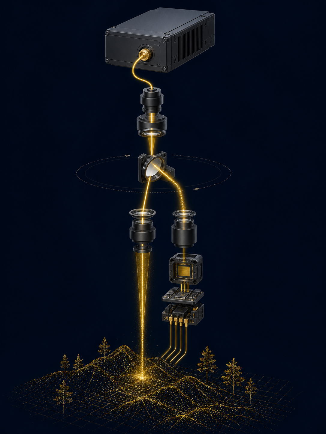
Un láser de fibra pulsada crea una forma de onda semilla controlada y la amplifica a través de una ruta de ganancia basada en fibra. El ancho de pulso de salida, la potencia pico, la tasa de repetición y la potencia promedio deben seleccionarse juntos porque determinan la entrega de energía óptica, la carga térmica y el margen de temporización del sistema de detección final.
Sincronización de pulsos
La semilla define la referencia de sincronización y la forma inicial del pulso para el sistema.
Ruta de ganancia de fibra
La amplificación eleva el pulso óptico a la clase de potencia máxima requerida.
Interfaz de conector
La selección del conector de fibra debe coincidir con la óptica del host, el control de contaminación y las necesidades de servicio.
Disparo externo
La sincronización del host, la conexión a tierra eléctrica y el comportamiento del disparador deben validarse juntos.
Conocimiento de selección
Cuatro parámetros vinculados definen la envolvente de pulso utilizable.
Estas fuentes se seleccionan como parte de un sistema óptico. Utilice el receptor real, la arquitectura de escaneo, la pérdida óptica, la ruta térmica y la sincronización de adquisición de datos al elegir un modelo y su punto de operación.
Margen de señal
La potencia máxima afecta la intensidad óptica disponible durante el pulso. Evalúela junto con la sensibilidad del receptor, las pérdidas ópticas y la evaluación de seguridad del host.
Resolución de sincronización
El ancho de pulso contribuye a la resolución de tiempo de vuelo, mientras que el resultado práctico del sistema también depende del detector, la electrónica y el procesamiento de señales.
Densidad de puntos
La tasa de repetición influye en la cadencia de medición, la densidad de muestras, el rendimiento de datos y la carga térmica total en el instrumento final.
Presupuesto térmico
La potencia óptica media y la entrada eléctrica definen los requisitos de enfriamiento y suministro de energía. No dimensione la ruta térmica solo en torno a la potencia máxima.
Energía de pulso ≈ potencia máxima × ancho de pulso
Use unidades consistentes: 1 kW × 1 ns ≈ 1 µJ. Esta es una relación de selección de primer orden; la energía de pulso real entregada y las combinaciones de operación disponibles deben tomarse de la especificación técnica del modelo elegido.
Soluciones de aplicación
Diseñado para arquitecturas LiDAR civiles, industriales y científicas.
El rendimiento de la aplicación proviene de todo el instrumento: fuente, óptica de transmisión, escáner, receptor, electrónica de sincronización, calibración y entorno operativo. Apoyamos la selección de modelos en torno a esa cadena completa.
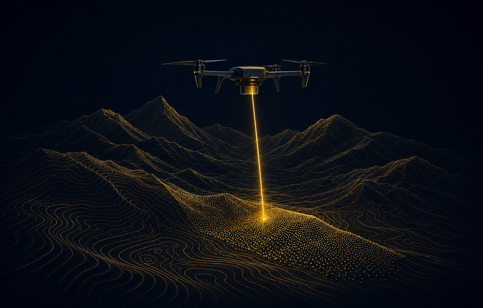
01 / MAPEO DE TERRENO
Mapeo de terreno
Integración de fuente LiDAR aerotransportada para levantamientos topográficos y generación de modelos de terreno.

02 / INFRAESTRUCTURA
Corredores ferroviarios y de infraestructura
Arquitecturas de fuente pulsada para ferrocarril, carretera einfraestructura de medición.

03 / INDUSTRIAL
Mapeo móvil industrial
Fuentes ópticas compactas para escaneo móvil y medición espacial industrial.
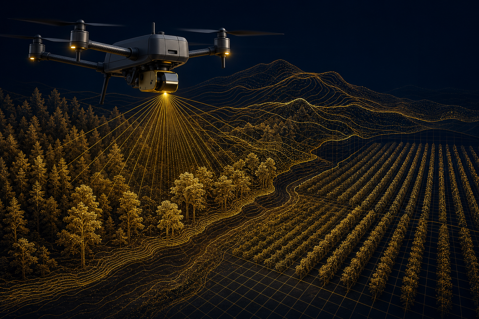
04 / SILVICULTURA Y AGRICULTURA
Silvicultura y agricultura
Flujos de trabajo LiDAR aerotransportados para estructura de dosel, relieve y mapeo agrícola.
Integración mecánica y eléctrica
Resuelva las interfaces de fibra, disparador, energía y térmica antes de fijar el gabinete del host.
Use el dibujo específico del modelo, la definición del conector y los límites de operación como base de diseño. Valide el sistema host ensamblado, incluido el enrutamiento de fibra, la gestión de curvatura, el ruido eléctrico, la transferencia térmica y el acceso de servicio, en lugar del láser desnudo de forma aislada.
Limpie, proteja, alinee
Haga coincidir la interfaz FC/APC o FC/UPC con la óptica del host y proteja las caras de los extremos de la contaminación.
Sincronice el sistema
Confirme la polaridad del disparo, el retardo, la fluctuación y la conexión a tierra con la documentación del modelo seleccionado.
Suministro de 9–13 V
Verifique el arranque, la capacidad de corriente, la ondulación y la caída del cable, no solo el voltaje.
Construya la ruta de disipación de calor
Proporcione contacto controlado con el chasis y pruebe la temperatura en el punto de operación real instalado.
Pruebas y control de calidad
Los controles a nivel de fuente se centran en el pulso, la entrega óptica y la fiabilidad relevante para la integración.
El plan de aceptación detallado y la calificación ambiental se definen para la configuración cotizada. Solicite el registro aplicable y el alcance de la prueba al planificar muestras o entrega en volumen.
Longitud de onda
Verifique la salida de la fuente contra la especificación del modelo seleccionado de 1535 nm o 1550 nm.
Salida de pulso
Verifique la potencia del pulso y la salida promedio en el punto de operación definido.
Comportamiento temporal
Verifique el ancho del pulso, la relación con el disparo y el comportamiento de repetición según corresponda.
Entrega por fibra
Inspeccione la condición del conector óptico y la estabilidad de salida en la interfaz de la fibra.
Cribado ambiental
El alcance de temperatura, vibración y envejecimiento se define por el plan de calificación del proyecto.
Entrega trazable
La identificación del modelo, la trazabilidad del número de serie y la información de inspección de salida pueden acompañar al envío.
Seguridad y cumplimiento: el láser de fibra pulsada es una fuente OEM. El instrumento completo es responsable de la clasificación final de seguridad láser y de cualquier aprobación aplicable en su configuración óptica y de operación final.
Preguntas frecuentes previas a la venta
Aclare las entradas del sistema antes de solicitar muestras.
Estas preguntas hacen que la discusión técnica sea más productiva y nos permiten recomendar la configuración de fuente, los documentos de integración y la ruta de validación correctos.
¿Cómo elijo entre 1535 nm y 1550 nm?
Comience con la sensibilidad del receptor, la óptica de transmisión, la elección del detector, la ruta atmosférica, la evaluación de seguridad final y la arquitectura del sistema existente. La longitud de onda debe seleccionarse para el sistema completo, no solo a partir de un número de potencia máxima.
¿Qué me dice la potencia máxima?
Indica la potencia óptica instantánea durante el pulso. Debe leerse junto con el ancho del pulso, la tasa de repetición, la potencia promedio, la entrega por fibra y el margen de señal del receptor. No es una medida independiente del alcance final del sistema o de la calidad de la nube de puntos.
¿Puedo seleccionar cualquier combinación de ancho de pulso y tasa de repetición?
No. Los valores en esta página identifican configuraciones publicadas. Las combinaciones disponibles, el comportamiento de disparo y los límites de rendimiento se confirman en la especificación técnica del modelo seleccionado.
¿Qué salida de fibra debo usar?
El modelo de 1535 nm 1.2 kW lista FC/APC + FC/UPC; los dos modelos de 1550 nm listan FC/APC. El conector, el enrutamiento de la fibra, el radio de curvatura, la limpieza y la compatibilidad óptica aguas abajo deben verificarse durante el diseño.
¿Qué información del host se necesita para una recomendación de muestra?
Proporcione la aplicación objetivo, la preferencia de longitud de onda, el régimen de pulso y repetición deseado, el diseño óptico del host, el tipo de receptor, el riel de alimentación, la ruta térmica disponible, el volumen del gabinete, la temperatura de operación y la fecha de evaluación planificada.
¿Puede Lumexis soportar integración personalizada?
Podemos evaluar solicitudes OEM en torno a la salida óptica, la interfaz mecánica, la conexión eléctrica, la configuración del disparo y la documentación del programa. La viabilidad depende del rendimiento solicitado, el alcance de la validación y el requisito de producción.
Inicie una revisión de fuente OEM
Seleccione la fuente pulsada teniendo en cuenta el sistema LiDAR completo.
Envíe su longitud de onda requerida, régimen de pulso, receptor y diseño óptico, envolvente mecánica, suministro eléctrico y condiciones térmicas. Identificaremos los modelos relevantes y los documentos de ingeniería para la evaluación.