Una plataforma de fuente pulsada de Er:Glass para sistemas ópticos OEM seleccionados.

Lumexis desarrolla fuentes láser compactas de vidrio de erbio pulsado para OEM telemetría, detección óptica, LiDAR e instrumentos científicos. La serie abarca energía de pulso de 40–500 µJ a 1535 nm, con ancho de pulso de 3–6 ns, frecuencia de repetición de 1–1000 Hz según el modelo, divergencia ≤10 o ≤15 mrad, fuente de alimentación <2 V y operación de −40 a +65°C.
Los valores de rendimiento son específicos del modelo. Confirme la especificación técnica específica del pedido, la interfaz y el dibujo de integración antes de la liberación del diseño.
 Telemetría OEMLiDAR y teledetecciónDetección ópticaInstrumentos científicos
Una plataforma de fuente pulsada de Er:Glass para sistemas ópticos OEM seleccionados.
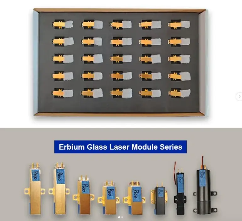
Seis modelos de fuente proporcionan un rango de energía definido para compensaciones del sistema.
Salida de pulso corto especificada en toda la serie de modelos publicados.
Seleccionada por modelo: 1–10 Hz o 1000 Hz para la fuente de 40 µJ.
Divergencia dependiente del modelo que debe coincidir con la trayectoria óptica del sistema anfitrión.
Rango de temperatura de operación publicado; confirme la configuración final.
Gama completa de productos
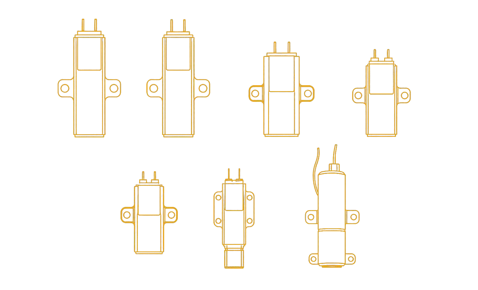
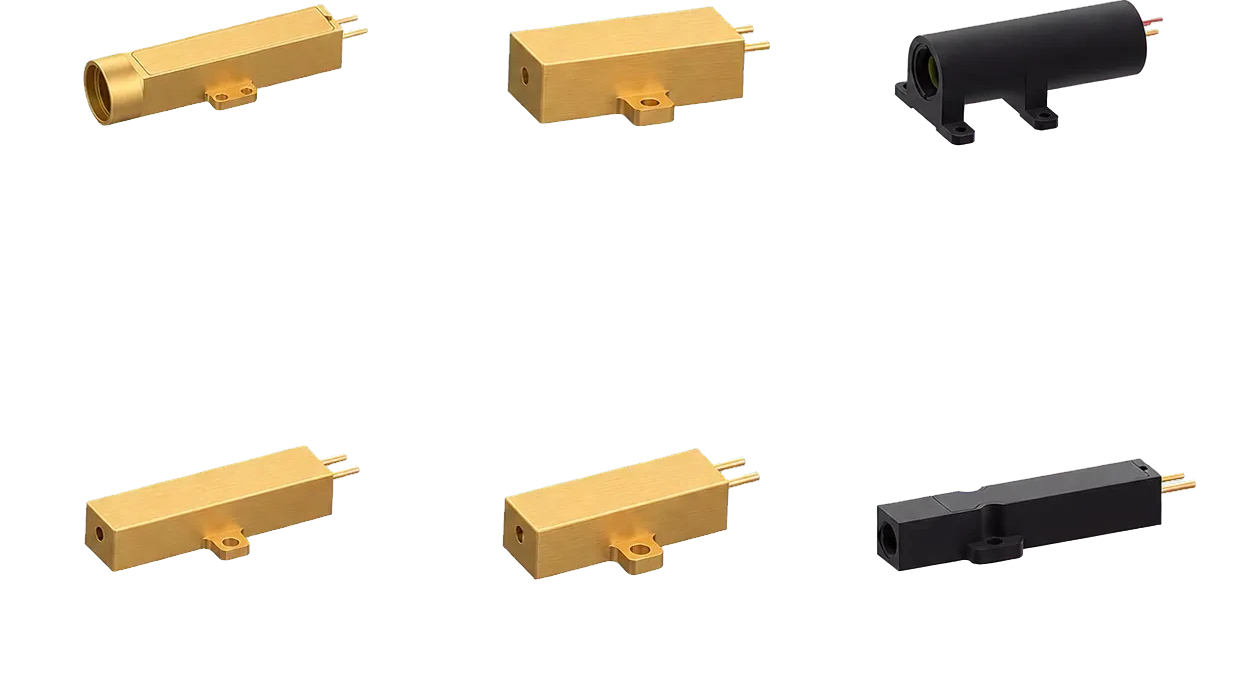
Todos los modelos publicados se muestran a continuación. Comience con la energía de pulso requerida, la frecuencia de repetición, la divergencia del haz y el volumen de instalación disponible; luego verifique la interfaz eléctrica, el dibujo mecánico y la condición de prueba para el sistema previsto.
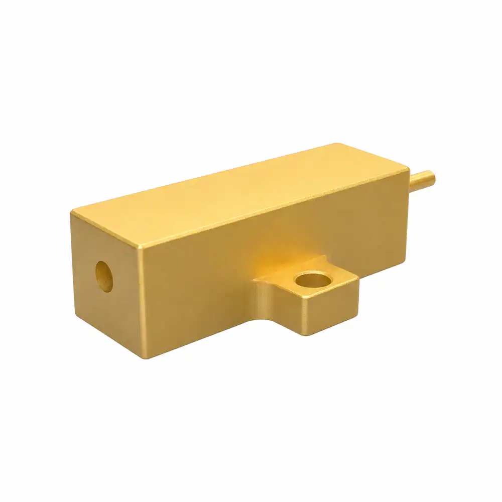
1535-LXER040
40 µJ a 1535 nm; repetición de 1000 Hz; ancho de pulso de 3–6 ns; divergencia ≤15 mrad.
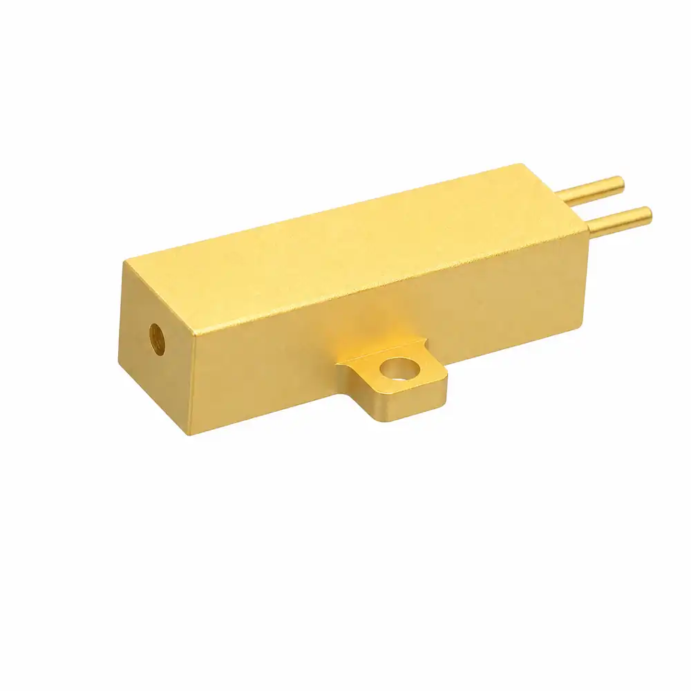
1535-LXER100
100 µJ a 1535 nm; repetición de 1–10 Hz; ancho de pulso de 3–6 ns; divergencia ≤10 mrad.
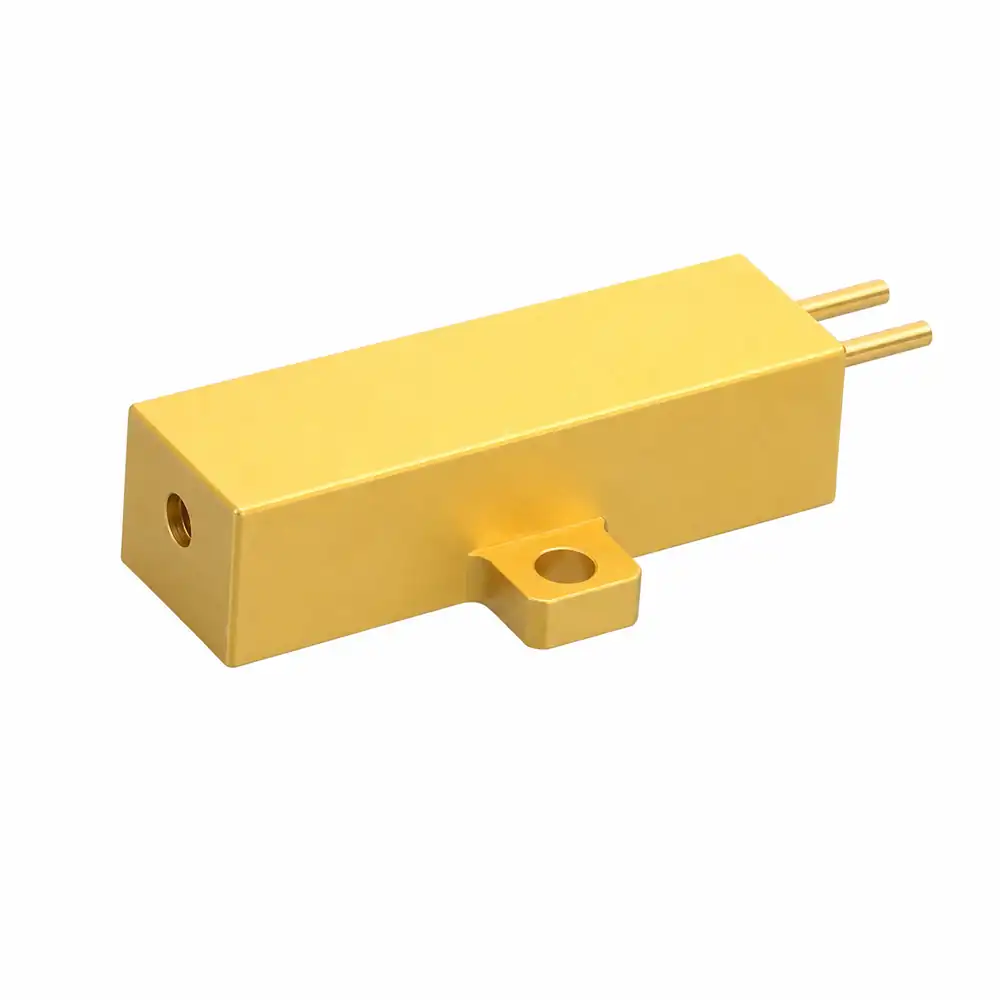
1535-LXER200
200 µJ a 1535 nm; repetición de 1–10 Hz; ancho de pulso de 3–6 ns; divergencia ≤10 mrad.
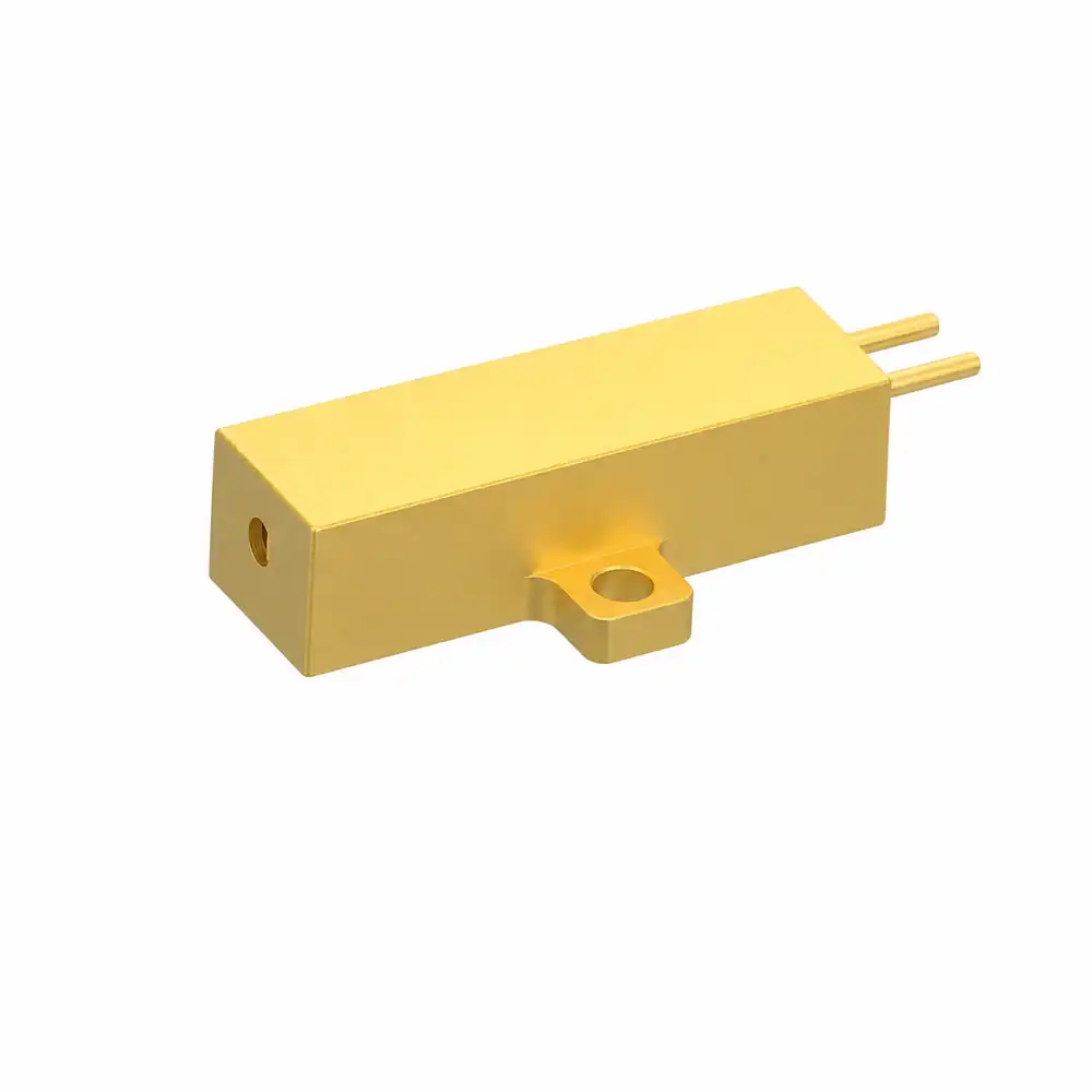
1535-LXER300
300 µJ a 1535 nm; repetición de 1–10 Hz; ancho de pulso de 3–6 ns; divergencia ≤10 mrad.
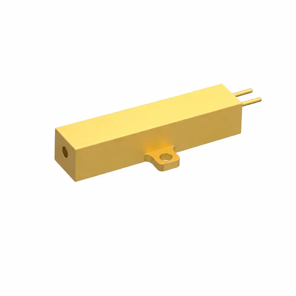
1535-LXER400
400 µJ a 1535 nm; repetición de 1–10 Hz; ancho de pulso de 3–6 ns; divergencia ≤15 mrad.
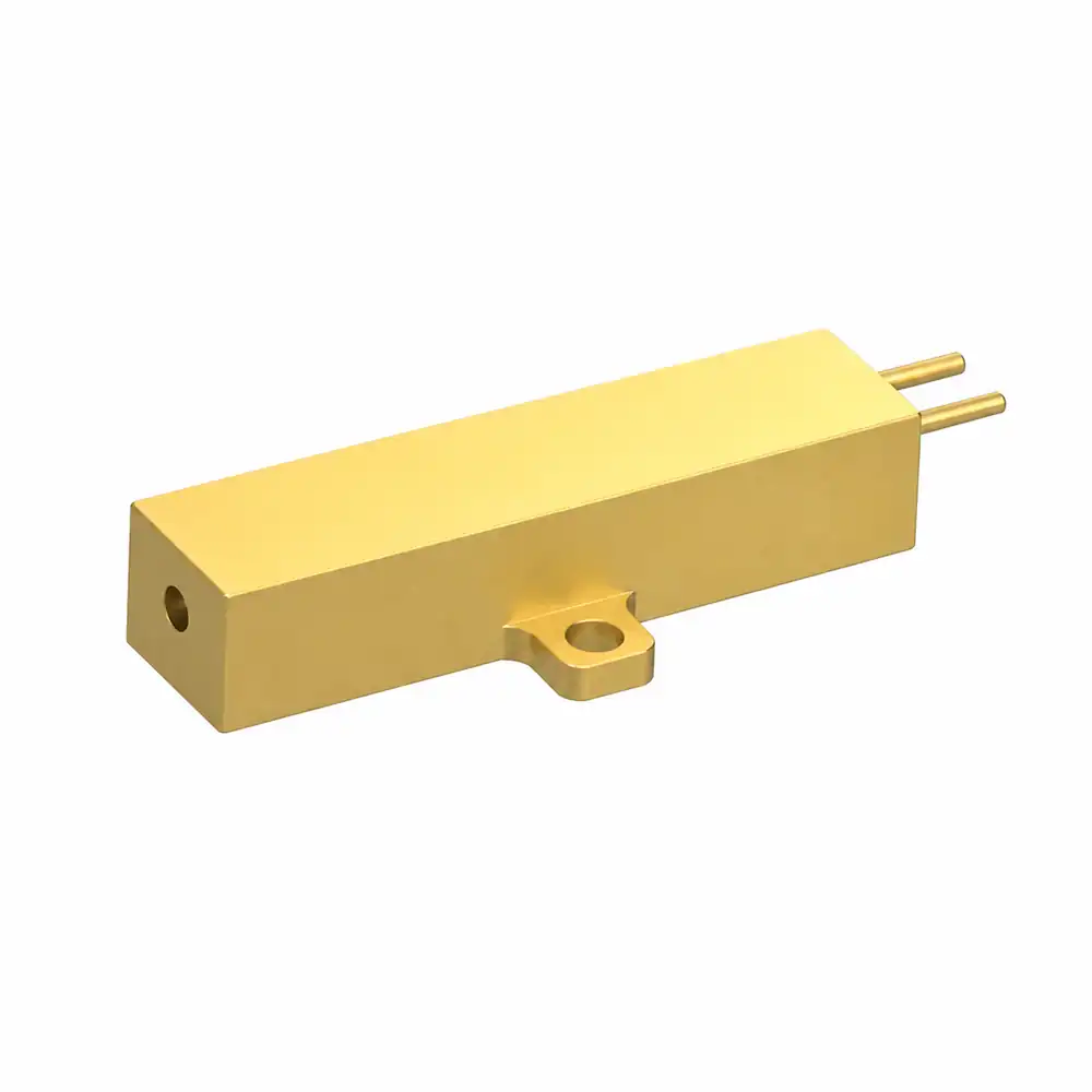
1535-LXER500
500 µJ a 1535 nm; repetición de 1–10 Hz; ancho de pulso de 3–6 ns; divergencia ≤15 mrad.
Comparación de modelos
La tabla es una ayuda de selección, no un documento de liberación de integración. La interfaz, el envolvente mecánico y las condiciones de prueba se confirman en la especificación técnica específica del modelo.
| Modelo | Energía de pulso | Repetición | Ancho de pulso | Divergencia | Alimentación | Temperatura de operación | Peso |
|---|---|---|---|---|---|---|---|
| 1535-LXER040 | 40 µJ | 1000 Hz | 3–6 ns | ≤15 mrad | <2 V | −40 a +65°C | — |
| 1535-LXER100 | 100 µJ | 1–10 Hz | 3–6 ns | ≤10 mrad | <2 V | −40 a +65°C | 9 g |
| 1535-LXER200 | 200 µJ | 1–10 Hz | 3–6 ns | ≤10 mrad | <2 V | −40 a +65°C | 9 g |
| 1535-LXER300 | 300 µJ | 1–10 Hz | 3–6 ns | ≤10 mrad | <2 V | −40 a +65°C | 9 g |
| 1535-LXER400 | 400 µJ | 1–10 Hz | 3–6 ns | ≤15 mrad | <2 V | −40 a +65°C | 11 g |
| 1535-LXER500 | 500 µJ | 1–10 Hz | 3–6 ns | ≤15 mrad | <2 V | −40 a +65°C | 13 g |
Nota de especificación: Longitud de onda de 1535 nm, energía de pulso, tasa de repetición, ancho de pulso y valores de divergencia son valores publicados específicos del modelo. “—” significa que la fuente de datos pública no lista un valor; solicite la hoja de datos relevante para el modelo seleccionado.
Fundamentos de la fuente láser
La energía se almacena en el medio de ganancia de vidrio dopado con erbio y se libera como un pulso óptico corto cuando el conmutador Q pasivo cambia la pérdida del resonador. La energía del pulso resultante, el ancho, la divergencia del haz y la tasa de repetición son parámetros de diseño interdependientes, no ajustes independientes para optimizar de forma aislada.
El vidrio activo almacena energía de bombeo y proporciona la transición láser de 1535 nm.
Admite operación pulsada compacta sin un conmutador Q accionado externamente.
La óptica de salida establece la geometría del haz entregado para la ruta óptica del sistema anfitrión.
Los detalles de montaje, conector y apertura deben seguir el dibujo del modelo seleccionado.
Conocimiento de selección
Una fuente debe evaluarse como parte del sistema óptico y eléctrico completo. Estas entradas ayudan a definir la lista inicial de modelos y las preguntas de ingeniería para las pruebas de muestras.
La energía de pulso establece la energía óptica disponible por emisión. Selecciónela según el margen de señal requerido del sistema, la sensibilidad del receptor, las pérdidas ópticas y la evaluación de seguridad final.
La divergencia controla la rapidez con la que se expande el haz. Un expansor anfitrión, una apertura y la tolerancia de alineación influyen en la huella entregada.
La tasa de repetición debe coincidir con el tiempo de adquisición, el presupuesto térmico y el procesamiento del anfitrión. El modelo de 40 µJ se especifica a 1000 Hz; otros modelos listados son de 1–10 Hz.
Los pulsos más cortos pueden soportar la resolución de tiempo de vuelo, pero la respuesta completa del sistema también incluye los límites del detector, la electrónica, el tiempo y el procesamiento de señales.
Para ángulos pequeños, use la divergencia de ángulo completo θ en radianes y la distancia de propagación R. Incluya el diámetro inicial del haz de la fuente, la óptica del anfitrión y la tolerancia de alineación en el modelo detallado. Confirme la definición de divergencia en la especificación del modelo seleccionado.
Soluciones de aplicación
La idoneidad de la aplicación depende de la energía de pulso, la divergencia, la tasa de repetición, la ruta óptica del anfitrión y la arquitectura del receptor. Se recomienda realizar pruebas representativas del sistema antes del lanzamiento del diseño.
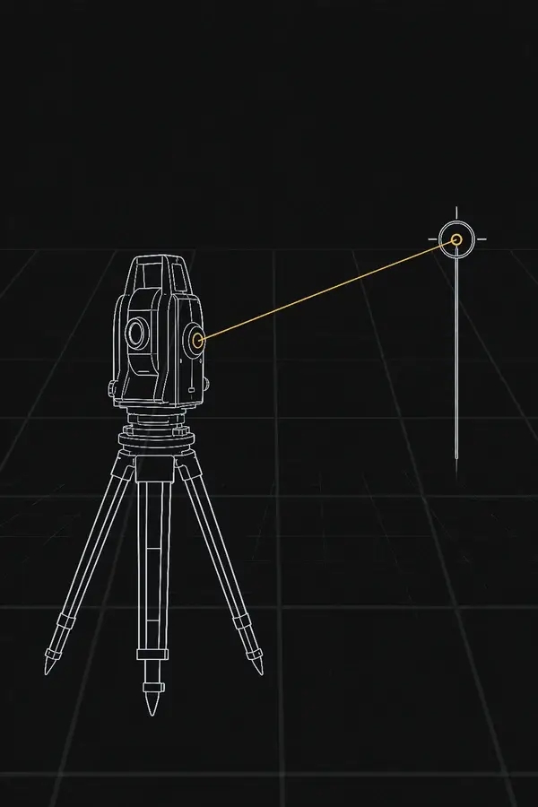
Bloque de construcción de fuente pulsada para instrumentos de medición compactos y subsistemas de medición integrados.
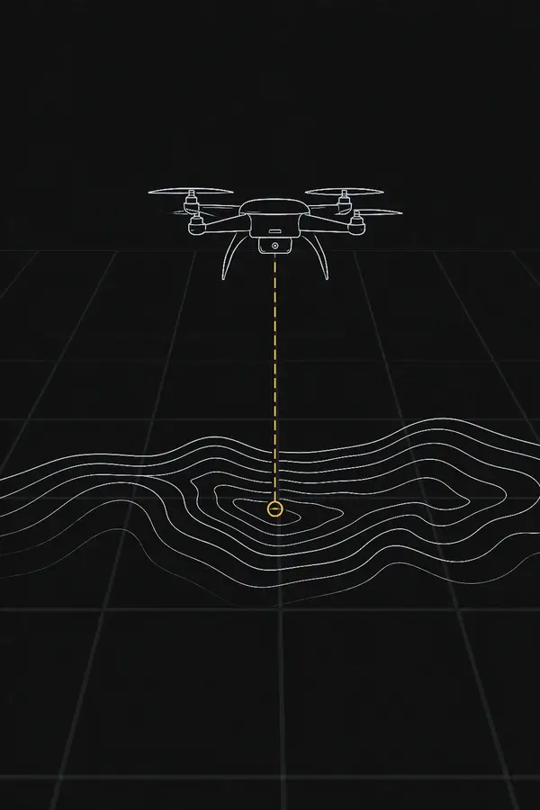
Integración de fuente para sistemas de mapeo civil que combinan transmisión pulsada, tiempo, escaneo y arquitectura de receptor.
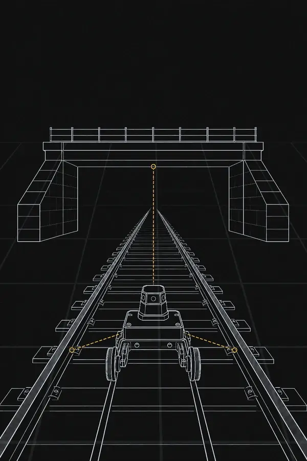
Admite flujos de trabajo de medición óptica para equipos de inspección ferroviaria y fija. infraestructura Equipos de inspección.
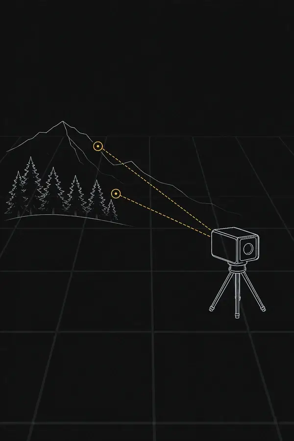
Una opción compacta de fuente pulsada de 1535 nm para instrumentación de investigación de laboratorio y campo.
Integración mecánica y eléctrica
Una fuente láser es solo una parte del instrumento final. Use el dibujo específico del modelo y la asignación de pines como base de integración, y valide el sistema ensamblado incluyendo óptica, montaje, cableado, estabilidad de suministro y entorno operativo.
Proteja la abertura de salida, mantenga una abertura libre y controle la alineación con el eje óptico del equipo anfitrión.
La especificación de fuente publicada indica una alimentación de <2 V. Confirme el arranque, la corriente de excitación y la conexión a tierra en la hoja de datos seleccionada.
Utilice el dibujo del modelo para localizar los puntos de fijación, las zonas de exclusión y las interfaces térmicas.
Pruebe el equipo anfitrión terminado, no solo la fuente desnuda, para verificar el rendimiento óptico y el cumplimiento de seguridad.
Fabricación, pruebas y entrega
El suministro repetible depende de un ensamblaje controlado, pruebas a nivel de modelo, confirmación de interfaces y embalaje protector. El plan de aceptación exacto y la documentación se definen para la configuración cotizada.
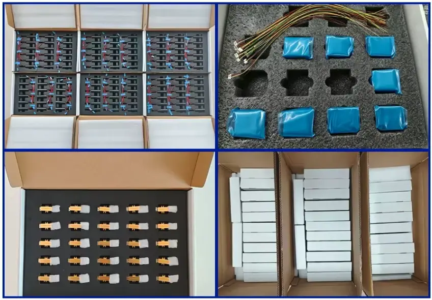
Verifique la salida según la especificación de fuente seleccionada de 1535 nm.
Mida la energía de salida contra el valor de aceptación relevante del modelo.
Verifique el ancho de pulso y el comportamiento de repetición para el modo de operación seleccionado.
Confirme la alineación y divergencia del haz contra el requisito del producto.
Confirme la identidad del modelo, los cables de interfaz, el estado del paquete y la documentación específica del pedido.
Separe las unidades de fuente y proteja las interfaces ópticas y eléctricas para la ruta de manejo.
Preguntas frecuentes previas a la venta
Estas respuestas proporcionan un punto de partida práctico para la selección de fuente y la cotización. Las interfaces exactas, los criterios de aceptación y los dibujos se confirman para el modelo seleccionado.
Comience con el presupuesto de enlace óptico del sistema, la sensibilidad del receptor, el margen de señal deseado, la transmisión de la óptica del equipo anfitrión, el requisito de alcance o detección y los límites térmicos/eléctricos. Una mayor energía de pulso no es automáticamente la respuesta correcta; el haz entregado, la cadencia de medición y la evaluación final del sistema importan en conjunto.
La especificación publicada de 1535-LXER040 indica 1000 Hz. Los modelos de 100–500 µJ listados en esta página se especifican a 1–10 Hz. Confirme el modo de operación requerido y el ciclo de trabajo en la hoja de datos del producto seleccionado.
Sí. Solicite la especificación técnica específica del modelo, el dibujo mecánico y la documentación de interfaz disponible durante la etapa de cotización o evaluación de muestras. Estos documentos deben usarse como la línea base de diseño en lugar de valores genéricos de la página de categoría.
Describe la dispersión angular del haz entregado. Influye en la huella del haz, el dimensionamiento de la abertura aguas abajo y la tolerancia de alineación. La óptica del equipo anfitrión puede dar forma adicional al haz, así que calcule la trayectoria óptica completa y verifíquela durante las pruebas del sistema.
Podemos evaluar requisitos OEM para la interfaz mecánica, la conexión eléctrica, la configuración óptica y la documentación del programa. La viabilidad depende del rendimiento solicitado, el volumen de producción, el alcance de validación y la aplicación final del equipo anfitrión.
Proporcione la aplicación objetivo, la energía de pulso requerida o el margen de señal, la tasa de repetición operativa, el diseño óptico del equipo anfitrión, el espacio y la masa disponibles, las condiciones de alimentación, el rango de temperatura esperado, la cantidad esperada y la fecha objetivo de validación.
No. La fuente es un componente OEM. El instrumento final debe evaluarse en su configuración óptica, eléctrica y operativa completa contra los requisitos aplicables de producto y seguridad láser.
Soporte de ingeniería
Envíe su objetivo de energía de pulso, tasa de repetición, diseño óptico, envolvente mecánica y condiciones operativas. Ayudaremos a identificar el modelo más adecuado y los documentos de ingeniería necesarios para la evaluación.