
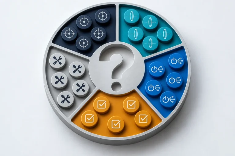
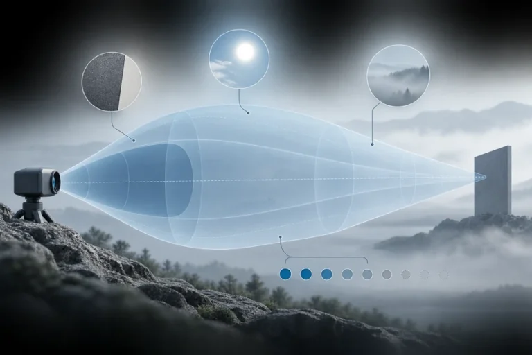

Ein OEM-Entfernungsmessprogramm kann Wochen verlieren, wenn “Genauigkeit” und “Reichweite” verglichen werden, ohne zu fragen, wie das Instrument die Entfernung ermittelt. Ein Phasenverschiebungsdesign und ein gepulstes Laufzeitdesign können beide eine Entfernung melden, doch ihre optischen Signale, Elektronik, Kalibrierungsarbeit und Fehlermodi sind unterschiedlich.
Die praktische Konsequenz ist einfach: Ein Sensor, der in einer kontrollierten Demonstration geeignet erscheint, kann eine sehr unterschiedliche Zielhandhabung, Mehrdeutigkeitskontrolle, Empfängerkonstruktion oder Host-Validierung erfordern, sobald er im endgültigen Instrument montiert ist.
Eine Entscheidung zwischen Phasenverschiebungs- und gepulstem Laser-Entfernungsmesser ist eine Wahl zwischen zwei Methoden zur Messung der Lichtlaufzeit. Phasenverschiebungssysteme leiten die Verzögerung aus der Phase einer intensitätsmodulierten Rückkehr ab; gepulste Laufzeitsysteme messen die Zeit eines zurückgekehrten optischen Pulses direkt. Keines ist universell besser. Wählen Sie basierend auf Ziel, Arbeitsentfernungsbereich, Aktualisierungsverhalten, Integrationsbeschränkungen und Nachweisen an Ihrem tatsächlichen Betriebspunkt.
Das Messprinzip verändert die technische Arbeit
Beide Ansätze beginnen mit derselben physikalischen Tatsache: Das optische Signal reist zu einem Ziel und ein Teil davon kehrt zum Empfänger zurück. Der Unterschied liegt darin, wie diese Hin- und Rücklaufverzögerung zu einem Entfernungswert wird.
Bei gepulster Laufzeit sendet der Sender einen kurzen optischen Puls. Der Empfänger erkennt das zurückgekehrte Signal und die Elektronik schätzt die verstrichene Zeit. In einem vereinfachten Modell ist die Entfernung die Hälfte der Lichtgeschwindigkeit multipliziert mit der Hin- und Rücklaufzeit. In einem realen Modul beeinflussen Pulsform, Detektorantwort, Schwellenwert- oder Zeitmessungsextraktion, Umgebungslicht, Zielreflexion und Kalibrierung das Ergebnis.
Die Phasenverschiebungsmessung verwendet ein kontinuierlich intensitätsmoduliertes optisches Signal. Die Rückkehr trägt eine Phasenverzögerung relativ zur gesendeten Modulation. Diese Phase ist proportional zur Reisezeit, wiederholt sich jedoch in ganzen Zyklen. Das Messsystem benötigt daher eine bewusste Mehrdeutigkeitsstrategie, die oft mehr als eine Modulationsfrequenz oder andere Einschränkungen verwendet. RP Photonics erklärt den Unterschied zwischen Pulszeitmessung und Phasenverschiebungs-Entfernungsmessung.
Wie gepulste Laufzeit-Entfernungsmesser funktionieren
Gepulste Designs geben der Elektronik ein Sendeereignis und ein Rückkehrereignis. Eine Zeitreferenz beginnt mit dem ausgehenden Puls oder einem überwachten Teil davon; der Empfängerkanal erzeugt das Rückkehrereignis. Das Modul schätzt die Entfernung aus der Verzögerung zwischen ihnen.
Das klingt direkt, aber “direkt” bedeutet nicht einfach. Eine schwache, breite oder verzerrte Rückkehr kann den gemessenen Zeitpunkt verschieben. Das vollständige System muss Sendestabilität, Empfängerempfindlichkeit, Detektorwiederherstellung, Zeitmessungs-Jitter, optische Ausrichtung und den Algorithmus, der eine gültige Rückkehr erklärt, verwalten. Hamamatsus technischer Überblick zeigt die übliche Abfolge: Ein kurzer Puls wird gesendet, eine Referenz etabliert den Start und ein schneller Detektor erzeugt das Rückkehrzeitereignis. Lesen Sie seine gepulste ToF-Erklärung.
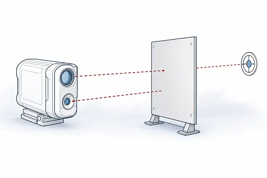
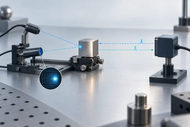
Typisches gepulstes Laufzeitkonzept. Gestrichelte optische Pfade sind konzeptionelle Kodierungen für nicht sichtbares Licht, keine spezifische Lumexis-Modularchitektur.
Was ein OEM für ein gepulstes Design validieren sollte
Beginnen Sie mit dem vollständigen Rückkehrpfad, nicht nur mit der Quelle. Definieren Sie Zielmaterial, Reflexion, Winkel, Arbeitsentfernung, Umgebungsbedingung und jedes Schutzfenster im Host-Gehäuse. Fragen Sie dann, wie das Modul eine Rückkehr definiert, unerwartete Rückkehren behandelt und sich verhält, wenn sich das Zielsignal ändert.
Die Host-Implementierung verdient gleiche Aufmerksamkeit. Überprüfen Sie das Versorgungsverhalten während Sendeereignissen, Erdung, Steckverbinderhaltung, mechanische Bezugsflächen, Wärmepfad, den Messauslöser und die Datenschnittstelle. Ein Ergebnis, das auf einer offenen Bank aufgezeichnet wurde, ist noch kein Nachweis für das fertige Instrument.
Wie Phasenverschiebungs-Entfernungsmesser funktionieren
In einem Phasenverschiebungssystem wird die gesendete optische Intensität mit einer bekannten Frequenz moduliert. Der Empfänger vergleicht die zurückgekehrte Modulation mit einer Referenz. Die gemessene Phase wird in Entfernung umgewandelt; für eine einzelne Modulationsfrequenz ist das eindeutige Intervall durch die Modulationsperiode begrenzt. Die Beziehung wird oft als Entfernung = cφ/(4πf) ausgedrückt, wobei c die Lichtgeschwindigkeit, φ die Phasendifferenz und f die Modulationsfrequenz ist. Es ist eine typische Beziehung, keine Produktspezifikation. Ein peer-reviewter Überblick beschreibt dieses indirekte Laufzeitmodell.
Die Methode kann gut für ein kontrolliertes Entfernungsintervall geeignet sein, in dem wiederholbare Phasenmessung wertvoll ist. Aber sie verlagert Komplexität in Modulationsqualität, Demodulation, Phasenkalibrierung, Umgebungslichtunterdrückung, optische Übersprechkontrolle und Mehrdeutigkeitsbehandlung. Ein Anbieter sollte den Frequenzplan und das Betriebsintervall hinter einem angegebenen Ergebnis beschreiben, anstatt eine Entfernungszahl ohne Bedingungen anzubieten.
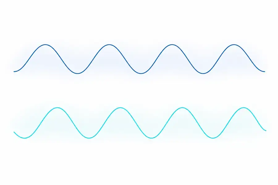
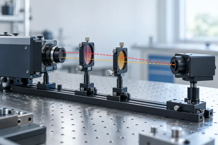
Nur konzeptionelle Phasenbeziehung. Die wellenformartigen Formen zeigen relative Verzögerung und enthalten keine gemessenen Daten, Frequenz oder produktspezifische Implementierung.
Fragen, die Phasenverschiebungs-Integrationsrisiken aufdecken
Fragen Sie, was die Phasenmehrdeutigkeit auflöst, welche Zieloberflächen während der Validierung verwendet wurden und wie das System über seinen Betriebstemperaturbereich kalibriert wird. Wenn das Modul hinter einem optischen Fenster sitzt oder ein Gehäuse mit anderen Lichtquellen teilt, bewerten Sie den installierten optischen Stapel. Rückreflexionen und interne Streuung, die auf einer Bank geringfügig erscheinen, können in einem phasenempfindlichen Messpfad wichtig sein.
Definieren Sie auch das Ergebnis, das Sie benötigen: Wiederholbarkeit, absoluter Fehler, Aktualisierungsverhalten oder Reaktion auf sich ändernde Zieloberflächen. Diese sind verwandte, aber unterschiedliche Abnahmekriterien. Das Datenblatt sollte die Bedingung für jede wesentliche Zahl angeben.
Phasenverschiebungs- vs. gepulster Laser-Entfernungsmesser: Vergleichstabelle
| Entscheidungsbereich | Gepulste Laufzeit | Phasenverschiebungsmessung |
|---|---|---|
| Entfernungsableitung | Direkte Zeitmessung eines reflektierten Pulses | Phasenverzögerung einer modulierten Rückkehr |
| Kernfokus der Elektronik | Schnelle Zeitreferenz und Rückkehrerfassung | Modulation, Demodulation, Phasenkalibrierung |
| Wichtiges Validierungsrisiko | Rückkehrerfassung ändert sich mit Signalbedingungen | Phasenmehrdeutigkeit und Phasenversatz über verschiedene Bedingungen hinweg |
| Nützliche Lieferantennachweise | Zielspezifische Rücklauftests und Zeitverhalten | Frequenzplan, Mehrdeutigkeitsmethode und kalibriertes Intervall |
| Fokus auf Host-Integration | Optischer Rückweg, Timing, Leistung und Schnittstelle | Optisches Übersprechen, Kalibrierstabilität und Referenzintegrität |
Lesen Sie diese Tabelle nicht als Reichweiten-Ranking. Die Eignung für Arbeitsdistanzen hängt von der Architektur, dem optischen Design, dem Detektor, dem Ziel, der Umgebung und dem geforderten Ergebnis ab. Ein technischer Überblick von 2020 trennt ebenfalls pulsbasierte direkte ToF von phasenbasierten indirekten ToF, anstatt sie als austauschbare Varianten zu behandeln. Siehe den Überblick.
Ein Auswahlprozess, der Prototypentests übersteht
Beschreiben Sie zunächst die Messaufgabe in technischen Begriffen: Zielgruppe, kleinste und größte Distanz, Zielwinkel, Akzeptanzunsicherheit, Aktualisierungsverhalten, Host-Umgebung, Schnittstelle und Betriebsumgebung. Die erforderliche Testmethode sollte gleichzeitig schriftlich festgehalten werden. Sie wird zur Grundlage für einen fairen Vergleich von Mustern.
Zweitens wählen Sie die Architektur, die die dominierende Einschränkung leichter handhabbar macht. Wenn breites Rücklaufzeitverhalten und ein gerichteter Messpfad dominieren, könnte ein pulsbasierter Ansatz natürlich passen. Wenn ein begrenztes Messintervall und eine phasenbasierte Auslesung zum Instrument passen, könnte Phasenversatz geeignet sein. Dies ist eine Systementscheidung, keine Abkürzung basierend auf einem einzelnen Parameter.
Drittens qualifizieren Sie das zusammengebaute Instrument. Beziehen Sie das Host-Fenster, die Blende, die Stromversorgung, die Kabelführung, die Montage und die vorgesehenen Ziele ein. Bestätigen Sie das Verhalten über den Temperaturbereich und die Hintergrundbedingungen, die für den Kunden relevant sind. Der nützlichste Bewertungsbericht erfasst Bedingungen ebenso sorgfältig wie Ergebnisse.
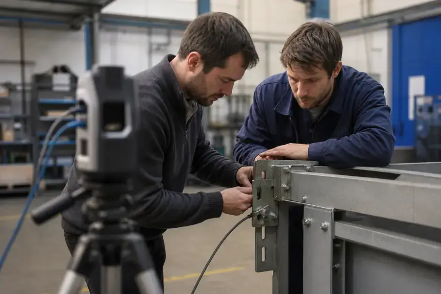
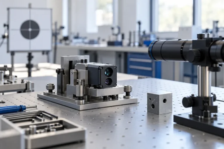
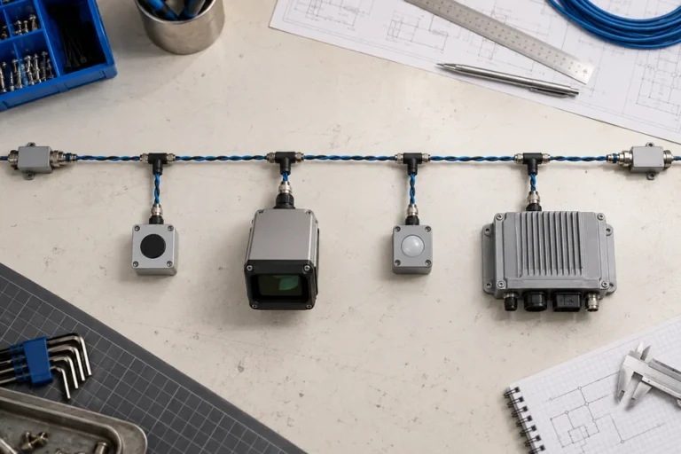
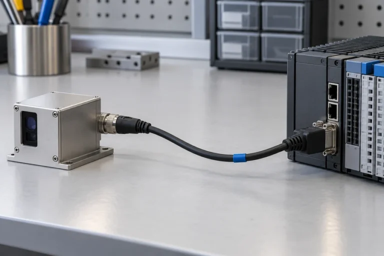
Konzeptioneller zivil-industrieller Integrationskontext, keine Kundeninstallation oder gemessener Testaufbau.
Worauf man bei einem Lieferanten für Entfernungsmessmodul achten sollte
Der Lieferant sollte in der Lage sein, die Messarchitektur auf der Ebene Ihrer Anwendung zu erörtern, nicht nur eine Schlagzeilen-Reichweite zu wiederholen. Fragen Sie nach den Testbedingungen hinter den gemessenen Ergebnissen, empfohlenen Host-Integrationspraktiken, Änderungskontrolle und einem Bewertungsplan von Muster bis Produktion.
Bei Lumexis entwerfen und fertigen wir Laser- Entfernungsmesser-Module für zivile Messung, industrielle Inspektion und wissenschaftliche Instrumente. Unser Team kann von Zielbedingungen und Integrationsbeschränkungen über optische, elektronische, mechanische und Validierungsabwägungen arbeiten. Unsere Technologiefähigkeiten beschreiben die technischen Disziplinen hinter dieser Arbeit, während unsere Lösungsseite den breiteren Anwendungskontext bietet.
Zuverlässige Produktion erfordert auch Kontrollen über eine Endproduktprüfung hinaus. Wareneingangsprüfung, Chiptests, Montage, optische Ausrichtung, wo anwendbar, Alterungsscreening und Endleistungstests bieten jeweils einen Punkt zur Steuerung von Variationen. Für einen OEM schafft das einen nützlicheren Weg vom ersten Muster zur wiederholbaren Lieferung.
FAQ
Ist Phasenverschiebung genauer als gepulste Laufzeitmessung?
Nicht als universelle Regel. Jede Methode kann für anspruchsvolle Messaufgaben entwickelt werden, aber das relevante Ergebnis hängt vom Ziel, Entfernungsintervall, Optik, Elektronik, Kalibrierung und Testbedingungen ab. Vergleichen Sie die Belege an Ihrem vorgesehenen Betriebspunkt, anstatt Architekturnamen oder nicht qualifizierte Schlagzeilenwerte zu vergleichen.
Warum benötigt ein Phasenverschiebungs-Entfernungsmesser eine Mehrdeutigkeitsbehandlung?
Phase ist periodisch. Eine gegebene gemessene Phase kann mehr als einer Ganzzyklus-Entfernung entsprechen, es sei denn, das System fügt Informationen hinzu, wie eine weitere Modulationsfrequenz oder ein kontrolliertes Betriebsintervall. Fragen Sie den Lieferanten, wie die Mehrdeutigkeit aufgelöst wird und welchen Entfernungsbereich die Validierung abdeckt.
Kann ein gepulster Entfernungsmesser nahe Ziele messen?
Er kann für bestimmte Entfernungsintervalle ausgelegt werden, aber das Verhalten bei nahen Zielen erfordert, dass die vollständige optische und elektronische Implementierung bewertet wird. Empfängerwiederherstellung, Sender-Empfänger-Trennung, Streulicht, Zeitgewinnung und Host-Fensterreflexionen können das Ergebnis beeinflussen. Testen Sie die vorgesehene Zielgeometrie, anstatt anzunehmen, dass eine Architektur jedes Intervall löst.
Welche Daten sollte ein OEM während der Bewertung anfordern?
Fordern Sie den Zieltyp, die Entfernung, den Zielwinkel, die Umgebungsbedingung, die Temperatur, die Versorgungsbedingung, das Aktualisierungsverhalten, die Messdefinition und die Unsicherheitsmethode hinter jedem Ergebnis an. Überprüfen Sie auch die Host-Schnittstelle, Montagerichtlinien, Annahmen zum optischen Fenster, Rückverfolgbarkeit und den vorgeschlagenen Produktionsabnahmetest.
Wenn Sie zwischen Phasenverschiebungs- und gepulsten Laser-Entfernungsmessern für ein OEM-Programm wählen, kontaktieren Sie unser Entwicklungsteam mit Ihren Zielbedingungen, mechanischer Hülle, Schnittstelle und Validierungsanforderungen.
Referenzen
1. RP Photonics, “Entfernungsmessungen mit Lasern” — Puls- und Phasenverschiebungs-Messkonzepte. 2. Hamamatsu Photonics, “Entfernung mit Licht messen” — Überblick über direkte und indirekte Laufzeitmessung. 3. P. N. et al., “Pulsbasierte Laufzeit-Entfernungsmessung” — Beziehung zur phasenbasierten indirekten Laufzeitmessung. 4. Vergleich von Laufzeit- und Phasenverschiebungs-TLS-Intensitätsdaten — Vergleich der Messmethoden.