

Твердотельные лазеры выглядят просто на блок-схеме, однако подобрать такой лазер для реального прибора редко бывает просто. Знакомый диапазон длин волн или высокое значение пиковой мощности могут казаться подходящими, в то время как тепловая конструкция, поведение импульсов, определение пучка или метод квалификации делают источник непригодным.
Это руководство объясняет физику, не упуская из виду инженерные детали. Оно охватывает основные активные среды, схемы накачки и генерации импульсов, компромиссы по производительности, а также вопросы, которые команда OEM должна решить до выбора конструкции.
Твердотельные лазеры используют кристаллическую или стеклянную активную среду, содержащую активные ионы. Оптическая накачка возбуждает эти ионы, резонатор обеспечивает обратную связь, а вынужденное излучение создает управляемый пучок. Матрица и легирующая примесь определяют длину волны и поведение накопления энергии, в то время как накачка, резонатор, тепловой путь и метод генерации импульсов определяют рабочие характеристики системы.
Определение и область применения
Твердотельный лазер использует прозрачное твердое тело в качестве активной среды, обычно кристалл или стеклянную матрицу, легированную ионами редкоземельных или переходных металлов. Легирующая примесь обеспечивает полезные электронные переходы. Матрица удерживает эти ионы в стабильной физической структуре и сильно влияет на теплопроводность, механические свойства, спектральную ширину полосы и технологичность.
В обычной промышленной практике термин “твердотельный лазер” обычно означает объемный кристаллический или стеклянный лазер. Полупроводниковые лазеры также являются твердотельными, а оптическое волокно может содержать твердую легированную стеклянную сердцевину, но диодные лазеры и волоконные лазеры обычно рассматриваются как отдельные технологические семейства, поскольку их физика носителей, волноводные свойства, методы упаковки и масштабирования отличаются от объемных устройств [1].
Это различие важно при выборе источника. Лазер с диодной накачкой, или DPSS-лазер, использует полупроводниковый лазер в качестве накачки, но выходное излучение резонатора генерируется отдельной кристаллической или стеклянной активной средой.
Как работают твердотельные лазеры
Каждый твердотельный лазер требует выполнения трех функций: ввод энергии, оптическое усиление и обратная связь. Лампа или лазерный диод обеспечивают свет накачки. Активная среда поглощает часть этого света и накапливает энергию в возбужденных ионах. Зеркала вокруг среды образуют резонатор, при этом одно зеркало частично пропускает полезное выходное излучение.
Когда накачка создает достаточную инверсию населенностей, фотон на лазерном переходе может стимулировать возбужденный ион к испусканию другого фотона с той же частотой, фазовым соотношением и направлением. Многократные проходы через резонатор усиливают выбранные оптические моды, пока усиление не уравновесит потери в резонаторе и выходную связь.
Энергия испущенного фотона определяется по формуле:
E = hc / λЗдесь, E — энергия фотона, h — постоянная Планка, c — скорость света, а λ — длина волны. Это уравнение само по себе не определяет выходную длину волны; энергетические уровни легирующей примеси и матрицы, а также конструкция резонатора определяют, какой поддерживаемый переход будет генерировать излучение.
Накачка: импульсные лампы против лазерных диодов
Импульсные лампы обеспечивают широкополосный свет накачки и могут возбуждать относительно большие объемы активной среды, но значительная часть их спектра может выходить за пределы полезных полос поглощения. Лазерные диоды можно подобрать так, чтобы они лучше соответствовали полосе поглощения. Их компактный размер и управляемый драйвер также поддерживают создание более компактных и эффективных устройств.
Соответствие — это не просто запись длины волны на чертеже. Спектральная ширина и центральная длина волны накачки изменяются с током и температурой, в то время как активная среда имеет конечный спектр поглощения. Поэтому инженерный анализ должен сравнивать спектр накачки во всем рабочем диапазоне, а не только при комнатной температуре.
Геометрия накачки также влияет на производительность. Торцевая накачка может обеспечить сильное перекрытие мод накачки и резонатора. Боковая накачка может распределять энергию по большему объему. Ни один из вариантов не является универсально лучшим; решение зависит от желаемого размера моды, запасенной энергии, качества пучка, габаритов корпуса и пути отвода тепла.
Непрерывная и импульсная работа
Лазер непрерывного действия (CW) обеспечивает устойчивое выходное излучение в стационарных условиях. Импульсные конструкции высвобождают энергию за определенные интервалы времени. Не сравнивайте их только по выходной мощности.
Для последовательности импульсов:
Средняя мощность: P_avg = E_pulse × f_repE_pulse — энергия импульса, f_rep — частота повторения, а τ — длительность импульса при заданном соглашении о ширине. Выражение для пиковой мощности является оценкой, если не учитывается форма импульса. Два изделия с одинаковой средней мощностью могут предъявлять совершенно разные требования к оптическому повреждению, детекторам и тепловому режиму.
Модуляция добротности предотвращает генерацию, пока накапливается энергия накачки, а затем быстро снижает потери в резонаторе, чтобы высвободить короткий мощный импульс. Активные системы используют управляемый внутрирезонаторный модулятор; пассивные конструкции часто используют насыщающийся поглотитель. Синхронизация мод служит другой цели: она фиксирует фазовое соотношение между продольными модами для генерации гораздо более коротких последовательностей импульсов. Относитесь к “импульсному” как к категории, а не к полной спецификации [2].
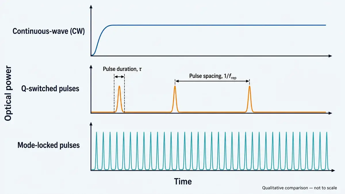
Выходное излучение CW является непрерывным, в то время как источники с модуляцией добротности и синхронизацией мод создают последовательности импульсов в очень разных временных масштабах. Качественное сравнение; не в масштабе.
Распространенные активные среды для объемных лазеров
Активный ион и матрица работают как пара. Замена матрицы при сохранении легирующей примеси может изменить поглощение, сечение вынужденного излучения, время жизни верхнего уровня, ширину полосы, теплопроводность и поляризационные свойства. Вот почему название материала никогда не должно заменять полную спецификацию источника.
| Активная среда | Типичная область выходного излучения | Инженерные характеристики | Типичное применение в одобренных областях |
|---|---|---|---|
| Nd:YAG | Около 1064 нм | Зрелая кристаллическая платформа с полезными тепловыми и механическими свойствами; поддерживает CW и импульсные конструкции | Промышленная накачка и научное оборудование |
| Nd:YVO4 | Около 1064 нм | Высокое усиление может поддерживать компактные генераторы с низким порогом; тепловое поведение требует тщательного проектирования | Научные приборы и компактные оптические источники |
| Yb:YAG | Ближний 1 мкм | Небольшая разница энергий между накачкой и лазером может снизить нагрев от квантового дефекта; часто используется в масштабируемых по мощности архитектурах | Промышленные источники накачки и исследовательские источники |
| Er:стекло | Область около 1,5 мкм | Стеклянная матрица поддерживает компактные форматы источников; тепловые и импульсные характеристики зависят от состава и корпуса | Прецизионное определение дальности, LiDAR и научное оборудование |
| Ti:сапфир | Широкая перестройка в ближнем инфракрасном диапазоне | Широкая полоса усиления поддерживает перестраиваемые и ультракороткоимпульсные исследовательские системы | Научное оборудование |
| Рубин | Около 694 нм | Исторически важный трёхуровневый лазер с относительно высоким порогом накачки | Исследования и обучение лазерной физике |
Эти диапазоны длин волн являются ориентировочными значениями, а не ограничениями для закупок. Точный выход зависит от состава материала, перехода, оптики резонатора, температуры и любого нелинейного преобразования частоты. Источник с удвоением частоты, например, следует рассматривать как полную архитектуру, а не описывать только по его видимой длине волны на выходе.
Стеклянные и кристаллические матрицы также создают разные компромиссы. Стекло может обеспечить гибкость состава, широкие спектры и адаптируемые формы, тогда как многие кристаллические матрицы обеспечивают более высокую теплопроводность. Широкая полоса пропускания может быть ценной для перестройки или коротких импульсов, но она может сопровождаться более низкими сечениями эмиссии или более слабыми тепловыми свойствами. Выбор активной среды — это задача оптимизации, а не ранжирование [3].
Почему эрбий-стеклянные лазеры заслуживают отдельного внимания
Er:стеклянный лазер — это объёмный твердотельный лазер, в котором усиление обеспечивает стекло, содержащее эрбий. Это не та же архитектура, что и волоконный лазер с эрбиевой легировкой, даже если их спектральные области перекрываются.
Для прецизионного определения дальности и научных приборов оценка источника должна связывать энергию импульса, ширину импульса, частоту повторения, расходимость, юстировку пучка, температурное поведение и отклик приёмника. Длина волны сама по себе не определяет дальность системы или лазерную безопасность. Готовое изделие должно оцениваться в его реальных условиях доступного излучения с использованием применимого стандарта и измерительной установки [4].
LUMEXIS разрабатывает эрбий-стеклянные лазерные источники как одну из наших четырёх основных технологических платформ. Наш более широкий подход к лазерным технологиям подход связывает оптическое проектирование с упаковкой, электроникой, прошивкой, терморегулированием и разработкой методов испытаний, а не рассматривает источник как изолированную оптическую деталь.
Объёмные лазерные архитектуры и их компромиссы
Объёмные активные среды могут быть выполнены в виде стержней, пластин, дисков или компактных микрочиповых структур. Геометрия управляет распределением накачки, модой резонатора, отношением поверхности к объёму, картиной напряжений, направлением охлаждения и практическим размером корпуса.
Стержень привычен и механически прост, но радиальные температурные градиенты могут вызывать тепловое линзирование и напряжения. Пластины распределяют тепло и могут поддерживать более широкий оптический путь, хотя резонатор и схема накачки становятся более сложными. Тонкодисковые конструкции отводят тепло в основном через короткое осевое направление, что может помочь в масштабировании мощности. Микрочиповые лазеры укорачивают и упрощают резонатор для компактных импульсных источников, но жёсткие допуски и малые оптические области повышают требования к покрытиям, юстировке и устойчивости к повреждениям.
Лучшая архитектура — та, которая остаётся стабильной в требуемой рабочей точке. Лабораторная демонстрация при номинальной температуре не доказывает, что резонатор сохранит выходную энергию, направление, размер моды и временные параметры импульса после прогрева или в заданном диапазоне условий окружающей среды.
Преимущества и ограничения объёмных лазерных источников
Твердотельные платформы могут сочетать компактную упаковку, широкий выбор длин волн, высокую накопленную энергию и точный временной контроль. Диодная накачка может улучшить электрическую и тепловую практичность по сравнению с широкополосной ламповой накачкой. Объёмные среды также могут обеспечивать большие площади оптических мод, чем многие волноводные устройства, что полезно, когда важна энергия импульса.
Ограничения не менее важны. Поглощённая мощность накачки, которая не выходит в виде полезного лазерного выхода, превращается в тепло. Температурные градиенты изменяют показатель преломления, создают напряжения и могут деформировать оптические поверхности. Результатом может быть тепловое линзирование, деполяризация, ухудшение пучка, нестабильность резонатора, дрейф длины волны или снижение срока службы компонентов [3].
Резонаторы со свободным пространством также зависят от юстировки. Механическое перемещение, поведение клеев, загрязнение покрытий, напряжения припоя и тепловое расширение могут смещать характеристики, даже если каждый отдельный компонент прошёл входной контроль. Надёжность должна быть спроектирована в оптический, механический, электрический и тепловой стек вместе.
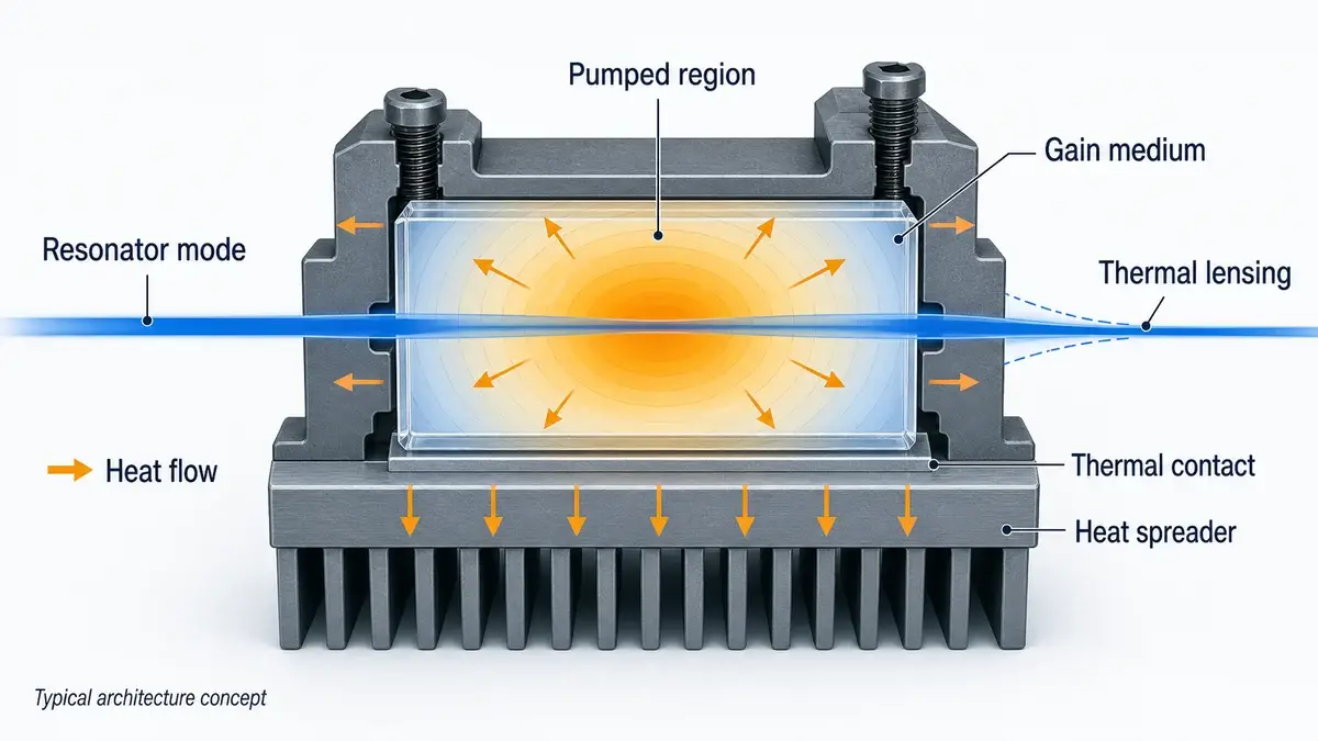
Качественный разрез объёмного лазера, показывающий, как тепло может распространяться от области накачки в крепление, в то время как температурный градиент изменяет моду резонатора. Типичная концепция архитектуры.
Как выбрать твердотельный лазер
Начните с оптической задачи, а не с предпочтительной активной среды. Определите, что источник должен выдавать на интерфейсе системы и при каких условиях. Длина волны — это только первый этап.
Укажите выходные параметры полными наборами
Для непрерывной работы укажите оптическую мощность с рабочей температурой, условиями управления, поведением при прогреве, диаметром пучка, расходимостью или M², поляризацией и интервалом стабильности. Для импульсной работы держите вместе энергию импульса, длительность, частоту повторения, среднюю мощность, временной джиттер и стабильность от импульса к импульсу.
Уточните, как измерялось каждое значение. “Диаметр пучка” может относиться к ширине 1/e², FWHM или другому определению. Расходимость может быть полным или половинным углом. Ширина импульса может быть FWHM, в то время как расчёт пиковой мощности предполагает прямоугольный импульс. Эти несоответствия могут привести к ошибкам в оптике, насыщению приёмника или тепловым бюджетам.
Моделируйте интерфейсы
Источник взаимодействует с управляющей электроникой, монтажными поверхностями, радиаторами, оптикой, детекторами, прошивкой и корпусом. Задокументируйте допустимые ток и напряжение, уровни триггера, заземление, распиновку разъёмов, плоскостность монтажа, тепловое сопротивление, положение оптической оси и воздействие обратного отражения.
Для конструкции с диодной накачкой качество накачки требует той же дисциплины. Размер сердцевины волокна, числовая апертура, формат разъема или сращивания, эффективность связи, поведение длины волны от температуры и управление обратным светом — все это влияет на подаваемую мощность накачки и срок службы. Наши решения с волоконно-связанными лазерами разработаны вокруг контролируемой доставки луча и интеграции, а не изолированной мощности излучателя.
Проверьте реальное рабочее окно
Типовые значения при комнатной температуре не являются планом квалификации. Запрашивайте данные при соответствующей температуре, рабочем цикле, частоте повторения, условиях монтажа и состоянии прогрева. Если прибор работает динамически, включайте переходные процессы, а не измеряйте только после установления равновесия.
Термоциклирование может выявить смещения юстировки и напряжение в межсоединениях. Приработка или скрининг старения могут помочь выявить отказы на раннем этапе. Герметичная упаковка может быть актуальна, когда влага или загрязнения могут повлиять на покрытия, поверхности или соединения, но конструкция корпуса и доказательства проверки на герметичность должны подтверждать это утверждение.
Проверьте лазерную безопасность на уровне продукта
Никогда не определяйте класс безопасности только по длине волны. Классификация зависит от доступного излучения, характеристик импульсов, продолжительности воздействия, апертуры, геометрии луча, поведения сканирования и конструкции продукта. IEC 60825-1 охватывает классификацию и требования для лазерных изделий в диапазоне от 180 нм до 1 мм; конечный производитель системы должен оценивать готовый продукт в соответствии с применимыми правилами [4].
Сравнивайте риск жизненного цикла, а не только цену за единицу
Более низкая цена покупки может быть сведена на нет термической переработкой, дрейфом в полевых условиях, несоответствующими партиями, длительными сроками замены или недокументированными изменениями процесса. Спрашивайте, что контролируется при входном контроле, сборке, юстировке, герметизации, скрининге и финальном тестировании. Прослеживаемость и контроль изменений являются коммерческими требованиями в той же степени, что и требованиями к качеству.
Просмотрите наши текущие портфель лазерных источников и модулей чтобы увидеть, как длина волны, архитектура источника и формат корпуса разделены на уровне продукта.
На что обратить внимание при выборе поставщика лазерных источников
Надежный поставщик должен преобразовать запрошенную основную спецификацию в проверяемое рабочее условие. Если вы запрашиваете энергию импульса, ответ должен также учитывать частоту повторения, определение длительности импульса, температуру, точку управления, метод выборки и допустимое отклонение. Если вы запрашиваете качество пучка, плоскость измерения и метод должны быть четкими.
В LUMEXIS наша команда связывает оптическое и оптомеханическое проектирование с упаковкой полупроводниковых лазеров, волоконной связью, электроникой, прошивкой, алгоритмами слабосигнальной дальнометрии и тепловым проектированием. Этапы производства могут включать входной контроль, тестирование чипов, монтаж кристаллов, пайку, юстировку, герметизацию, отбраковку при старении и финальное тестирование характеристик. Точный процесс зависит от источника и корпуса.
Для обсуждения квалификации запросите доказательства, относящиеся к вашему сценарию использования: данные о температурной зависимости, условия приработки, допуск на оптическую ось, схему измерения импульсов, прослеживаемость партий и критерии приемки. Общий сертификат или график при комнатной температуре не заменят этих деталей.
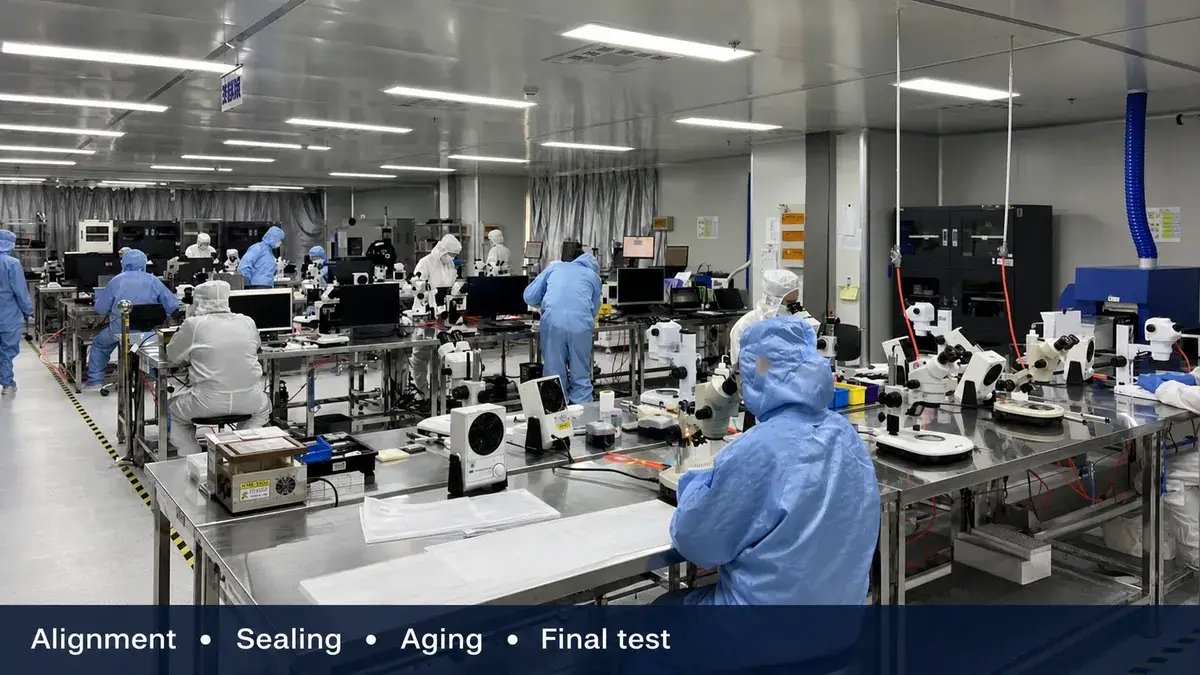
Контролируемая сборка, юстировка, герметизация, старение и финальное тестирование помогают преобразовать оптическую конструкцию в воспроизводимое серийное оборудование.
Часто задаваемые вопросы
В чем основное различие между твердотельным лазером и диодным лазером?
Обычный твердотельный лазер генерирует выходное излучение в легированном кристалле или стекле, которое накачивается оптически. Диодный лазер генерирует свет за счет рекомбинации электронно-дырочных пар в полупроводниковом переходе. DPSS-лазер содержит оба: диод обеспечивает накачку, а отдельная объемная активная среда формирует выходное излучение резонатора.
Является ли волоконный лазер твердотельным лазером?
Физически его легированное стеклянное волокно является твердым, поэтому волоконный лазер принадлежит к более широкому семейству твердотельных лазеров. В коммерческом и инженерном использовании волоконные лазеры обычно рассматриваются отдельно от объемных твердотельных лазеров, поскольку волоконный волновод управляет оптической модой, связью накачки, тепловым поведением, нелинейными эффектами и архитектурой корпуса.
Какие наиболее распространенные твердотельные лазерные материалы?
Распространенные среды включают Nd:YAG, Nd:YVO4, Yb:YAG, Er:glass, Ti:sapphire и рубин. Обозначение сочетает активный ион с матрицей, и оба важны. Сравните поглощение, длину волны излучения, ширину полосы, время жизни верхнего уровня, теплопроводность, механические свойства и требуемый режим CW или импульсный перед выбором.
Что такое лазер с модуляцией добротности на твердотельном лазере?
Лазер с модуляцией добротности накапливает энергию накачки в активной среде, пока потери резонатора поддерживаются высокими. Когда потери снижаются, накопленная энергия высвобождается в виде короткого импульса с высокой пиковой мощностью. Спецификация все равно требует энергии импульса, ширины, частоты повторения, средней мощности, стабильности и рабочих условий; “модуляция добротности” сама по себе неполна.
Почему управление теплом критично в твердотельных лазерах?
Не вся поглощенная энергия накачки становится лазерным выходом. Остаточное тепло создает температурные градиенты, которые могут изменять показатель преломления, вызывать механическое напряжение и деформировать поверхности. Эти эффекты могут влиять на качество пучка, юстировку, эффективность, импульсное поведение и срок службы, поэтому активная среда, крепление, путь охлаждения и резонатор должны проектироваться вместе.
Являются ли твердотельные лазеры на 1,5 мкм автоматически безопасными для глаз?
Нет. Длина волны влияет на то, как излучение взаимодействует с глазом, но сама по себе не определяет класс безопасности. Доступное излучение, энергия и длительность импульса, схема повторения, апертура, расходимость, условия экспозиции и защитные меры продукта — все это важно. Классифицируйте готовый лазерный продукт с использованием применимого стандарта и проверенных измерений.
Если вы выбираете объемный твердотельный источник, эрбий-стеклянный лазер или его архитектуру накачки, предоставьте нам рабочее окно и ограничения интерфейса, а не только целевую длину волны. Поговорите с нашими инженерами об источнике и пути квалификации, подходящих для прибора.
Ссылки
N. Hodgson и H. Weber, Твердотельная лазерная инженерия, CREOL, Университет Центральной Флориды: Твердотельные лазеры. R. Paschotta, RP Photonics Encyclopedia: Модуляция добротности. R. Paschotta, RP Photonics Encyclopedia: Активные среды лазеров и Тепловая линза. Международная электротехническая комиссия, IEC 60825-1:2014 — Безопасность лазерных изделий, Часть 1.