
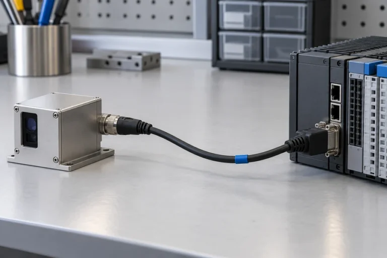

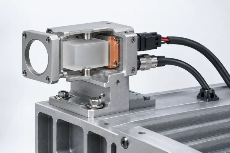




A port labeled RS-232 can look simple on a drawing and still fail during integration. The label does not tell you which endpoint owns each signal, whether a transceiver is already inside the module, how the connector is mapped, or what a valid distance reply looks like.
Lumexis develops and manufactures laser rangefinder modules for civil, industrial, and scientific systems. We treat the communication link as a controlled engineering boundary because a wiring assumption can become a field fault even when the ranging hardware itself is operating correctly.
An RS232 laser rangefinder module uses an RS-232 electrical link for point-to-point serial communication with a host. RS-232 defines signaling and interface characteristics, but it does not define the module pinout, baud rate, frame format, command set, distance units, timeout behavior, or measurement-validity rules. Those details must come from the released module documentation.
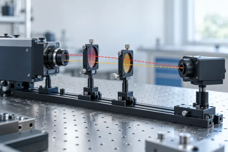
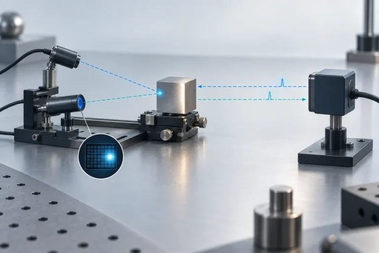
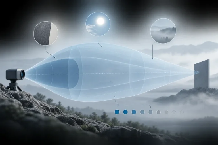
An RS232 laser rangefinder module has four interface layers
Start by separating four items that are often compressed into the word “serial.” The first is the exact module variant and connector. The second is the RS-232 physical layer between the endpoints. The third is the asynchronous byte format, such as bit rate, data bits, parity, and stop bits. The fourth is the application protocol that turns bytes into commands, status, and measurements.
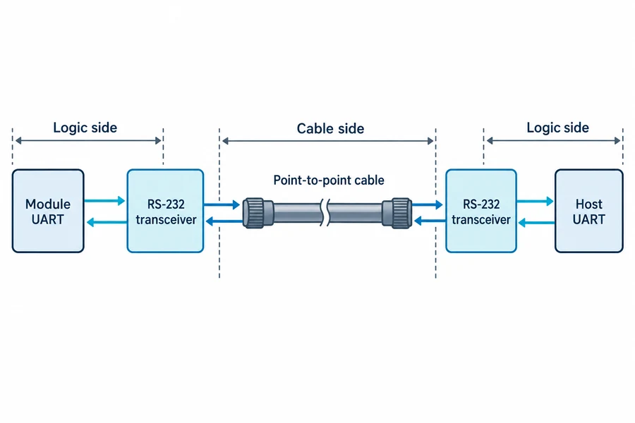
Texas Instruments describes RS-232 as a single-ended, point-to-point interface with electrical, functional, and mechanical characteristics. A UART, by contrast, creates and receives asynchronous character frames on the logic side. A transceiver can translate between a processor’s logic-level UART and the positive-and-negative voltage swing used on an RS-232 line.
That distinction matters because a host can be configured for the correct baud rate and still be electrically incompatible. It can also receive clean characters while interpreting the wrong protocol revision. Our laser rangefinder module interface comparison places RS-232 beside UART/TTL, RS422, and CAN so the physical-layer choice can be made from the installed system rather than from a familiar connector name.
Confirm the electrical boundary before connecting the host
Do not connect a microcontroller UART pin directly to a true RS-232 line. The logic-side pins and the cable-side pins belong to different voltage domains, and the RS-232 transceiver performs both level translation and polarity handling. Before wiring a sample, confirm where that transceiver sits for the exact module and host variants.
A useful interface-control record answers these questions:
- Does the module expose true RS-232 levels or logic-level UART signals?
- Which supply powers the transceiver, and what happens when one endpoint is unpowered?
- Which pins are transmit, receive, signal common, enable, or documented handshake lines?
- What connector orientation and pin numbering convention apply at each end?
- What protection is present at the cable-facing boundary?
- Is the port intended for normal operation, configuration, or service only?
The RS-232 line can swing below ground, so protection components must be selected for that behavior. Texas Instruments’ 2026 design guide also warns that pull devices and mismatched power states can create leakage paths or unexpected logic states. Review power sequencing, input bias, charge-pump capacitors, and any external bidirectional protection against the selected transceiver’s datasheet.
If the module exposes only logic-level serial, use the released electrical specification and the guidance in our UART для модуля лазерного дальномера. Do not infer “3.3 V,” “5 V tolerant,” or a safe direct connection from the word UART alone.
Freeze the DTE/DCE wiring and connector map
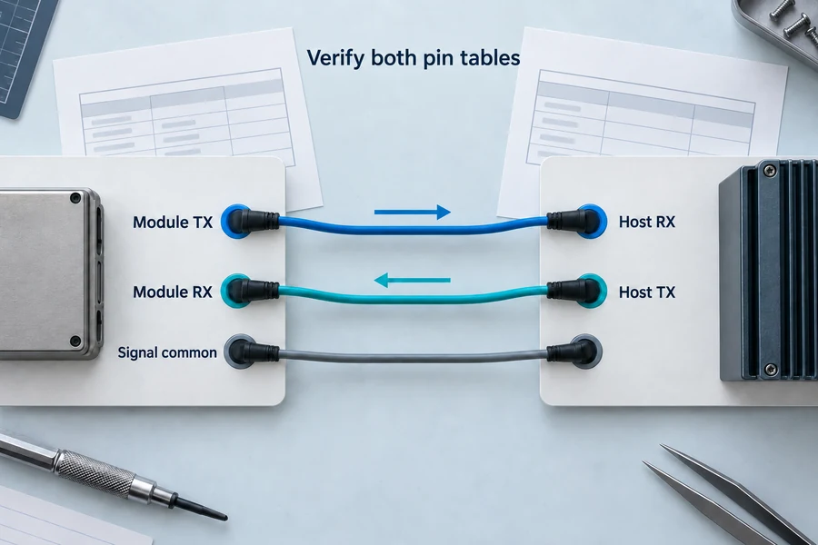
RS-232 documentation uses DTE and DCE roles to define signal direction. In a typical arrangement, transmitted data from one endpoint must reach received data at the other. The practical trap is that product documentation, breakout cables, USB adapters, and terminal software may describe TX and RX from different viewpoints.
Do not decide the wiring from connector gender alone. A DE-9 connector is common, but it is not required, and many embedded products use smaller connectors with product-specific pin assignments. A cable that is straight-through for one DTE/DCE pairing may need crossed data conductors for another pairing. The safe method is to write a two-column signal map from the documentation for both endpoints, then verify continuity on the actual cable assembly.
For a basic data link, the released design may use transmit, receive, and signal common. Hardware-handshake signals such as RTS and CTS should be included only when both endpoint specifications require them. Leaving required inputs floating or assuming that unused control lines are ignored can create intermittent startup behavior.
If the cable path is long, crosses noisy zones, or must tolerate more reference difference, compare the system requirement with a differential RS422 laser rangefinder link. RS-232 and RS422 may carry similar byte framing, but their electrical behavior and wiring are not interchangeable.
Treat byte framing and the ranging protocol as separate contracts
After the electrical link is correct, freeze the asynchronous character format. Record the bit rate, data bits, parity, stop bits, flow-control behavior, and startup state for the released module revision. A terminal that shows readable characters proves only part of the link.
The application protocol needs its own controlled record. Identify the frame boundary, length rule, command identifier, payload encoding, integrity field, response timeout, and representation of invalid or unavailable measurements. Record whether the module is polled for a single result, streams measurements, or supports both modes.
Build the host driver in layers. The transport layer should collect bytes, recognize a complete documented frame, reject malformed input, and resynchronize. The measurement layer should decide when a result is fresh, whether its status is usable, and what the rest of the system receives after a timeout or restart. Never let the last valid distance remain displayed or acted on as though it were a new reply.
This is one of the nine system boundaries covered in our laser rangefinder module integration guide. Keeping the parser separate from application logic makes protocol changes, diagnostic logging, and fault recovery easier to validate.
Cable load, routing, and protection set the installed margin
Avoid a universal cable-length promise. Modern RS-232 guidance treats cable capacitance, transceiver capability, data rate, and load as the practical limits. Analog Devices notes that the historical length figure was replaced by a maximum capacitive-load approach, which is more useful because real cables have different capacitance per unit length.
Review the complete installed path:
- selected transceiver’s guaranteed data rate and load conditions;
- cable capacitance and connector contribution;
- routing near switching supplies, motors, and high-current conductors;
- signal-common path and possible reference difference between enclosures;
- connector exposure to electrostatic discharge or hot insertion;
- protection capacitance and series resistance;
- shield connection strategy, if the system uses one.
Added capacitance or resistance can reduce available data-rate and cable margin. Place the transceiver and charge-pump components according to the device guidance, keep cable-facing protection compatible with bipolar signaling, and verify the result on the production-representative harness.
For civil measurement and industrial sensing systems, the communication interface should be evaluated alongside the optical window, mounting datum, thermal path, power rail, and host timing. Our обзор решений по лазерной дальнометрии shows how those constraints come together at system level.
Validate the complete link in three stages
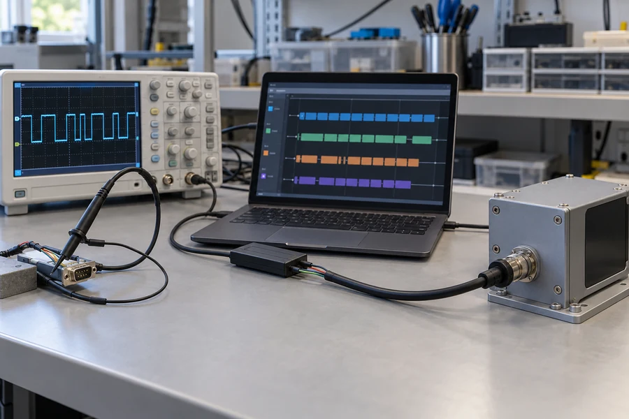
First validate the electrical boundary. Confirm idle polarity, signal swing, edge behavior, connector mapping, and power-state behavior with appropriate instruments and safe probing. Check both directions and repeat the test after disconnecting and reconnecting the cable.
Second validate byte and frame behavior. Exercise normal commands, partial frames, corrupted input, delayed replies, buffer boundaries, timeouts, and restart recovery. Capture raw traffic during development, but make sure diagnostic logging does not change timing enough to hide the fault.
Third validate the installed measurement path. Use the final host, cable, power supply, enclosure, firmware build, and operating sequence. Confirm that communication faults cannot turn an invalid or stale value into a valid range result. Record the module revision, protocol revision, cable drawing, host build, test conditions, and pass/fail rule together.
Our applications engineers can support selection, integration, validation, and troubleshooting across pre-sales and after-sales stages. Lumexis combines electronics and firmware work with optical, optomechanical, thermal, and test-method capability, supported by a vertically integrated production flow at our 14,000-square-meter Taizhou manufacturing base and engineering/commercial support in Wuxi. For custom or private-label projects, the Lumexis engineering service can help turn the interface assumptions into a released control document and acceptance plan.
When RS-232 is the right interface
RS-232 can be a practical choice for a documented point-to-point link to an industrial host, service computer, or controller that already supports the interface. It can simplify integration when both endpoints, cable, power states, and protocol are defined together.
It is not automatically the best choice for a shared network, a very long or electrically demanding path, or a host that only exposes logic-level UART. Choose from the system architecture first. The Lumexis laser rangefinder module family gives OEM teams a starting point for discussing interface, mechanical, optical, and validation requirements. Standard products can ship within three days when confirmed available; custom-product timing must be reviewed against the project scope.
Часто задаваемые вопросы
Is RS-232 the same as UART?
No. UART usually describes asynchronous byte framing on the logic side of a processor. RS-232 defines an electrical and interface standard for a point-to-point cable connection. A transceiver commonly translates between them. The module’s command protocol is a separate layer again.
Can an MCU UART connect directly to an RS-232 port?
Not when the exposed port uses true RS-232 levels. The positive-and-negative cable-side signals require a suitable transceiver before they reach the MCU’s logic-level UART pins. Verify both endpoint specifications because a product label may refer to the protocol loosely.
Do TX and RX always need to be crossed?
The transmit signal from one endpoint must reach the receive signal at the other, but whether the physical cable appears straight-through or crossed depends on the DTE/DCE roles and connector maps. Build the cable from the two released pin tables, not from a generic diagram.
How long can an RS-232 laser rangefinder cable be?
There is no responsible universal answer. The selected transceiver, data rate, cable capacitance, load, routing, reference conditions, and protection network all matter. Use guaranteed device limits and the actual cable specification, then verify the production-representative harness.
Is a DE-9 connector required for RS-232?
No. DE-9 connectors are common on industrial and computer equipment, but embedded modules may use compact product-specific connectors. Connector shape and gender do not prove signal direction or pin assignment, so the interface-control document remains authoritative.
What should the host do after a malformed or late reply?
Reject the frame, mark the measurement unavailable or invalid, resynchronize using the documented structure, and apply a controlled retry or recovery policy. Do not silently reuse the last valid distance. Log enough context to diagnose the event without disturbing real-time behavior.
Ссылки
- Texas Instruments, RS-232 Glossary and Selection Guide, May 2023.
- Texas Instruments, RS232 Design Guide, March 2026.
- Analog Devices, Fundamentals of RS-232 Serial Communications.
- Microchip, Getting Started with USART.
Send our инженерной команде the module variant, host port, connector map, cable specification, serial settings, protocol revision, power sequence, and operating environment. We can recommend a standard starting point, confirm three-day shipment for an available standard product, or review a custom or private-label interface with an applications engineer.