



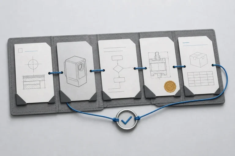
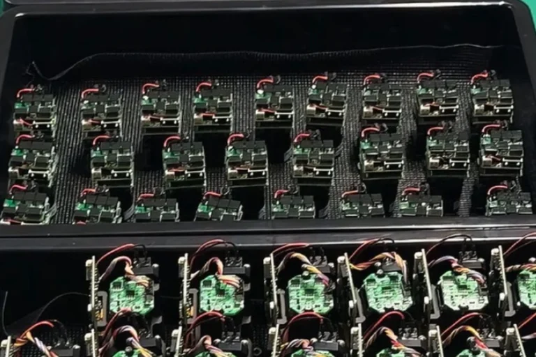




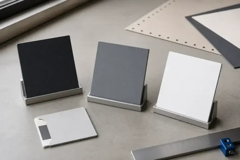

Selecting a ranging method from a single accuracy or range number is a common integration mistake. The useful comparison starts with the target, working distance, update rate, ambient light, mechanical envelope, power budget, and the way the host system will use a valid or invalid return.
**Direct ToF vs indirect ToF is a choice between measuring a light pulse’s round-trip delay and measuring the phase delay of intensity-modulated light.** Direct time-of-flight is often suited to discrete pulse timing and extended measurement intervals; indirect time-of-flight can provide fine distance resolution through phase measurement. Neither is inherently the better OEM choice without the application conditions.
Direct ToF vs Indirect ToF: the measurement difference
Direct time-of-flight, or dToF, sends a short optical pulse, detects returned light, and estimates its round-trip travel time. Distance follows from the speed of light and the measured delay divided by two. The practical challenge is detecting a useful, time-resolved return when the target is dark, angled, small, distant, or surrounded by competing reflections.
Indirect time-of-flight, or iToF, uses intensity-modulated illumination. The receiver compares the phase of the returned modulation with the transmitted reference. That phase shift represents travel distance, but a single modulation frequency repeats in phase. The architecture therefore needs an ambiguity strategy appropriate to the intended distance interval.
RP Photonics describes both direct pulse timing and phase-shift measurement as common laser-rangefinder principles. The distinction is more than vocabulary: it changes the source drive, receiver chain, timing or phase electronics, firmware, and validation method.
Where direct ToF is useful
Direct ToF is useful when the integration needs a discrete return-time measurement and can support the timing resolution and receiver sensitivity required by the target condition. In a rangefinder, the transmit pulse, detector, analog path, thresholding, and firmware all contribute to the reported result.
At longer working distances, weak returned light and beam divergence become increasingly important. Target reflectivity, spot size, receiver aperture, optical filtering, ambient light, and signal processing determine whether the return can be identified consistently. A headline range is therefore not a complete dToF specification; the target and test method belong beside it.
Where indirect ToF is useful
Indirect ToF can be attractive where high-resolution distance information is needed over a defined operating interval and the system can manage modulation, phase extraction, and ambiguity. Rather than directly resolving a short optical arrival time, the electronics estimate phase delay from a received modulated signal.
The design still faces real optical conditions. Ambient light, target reflectivity, multipath reflections, receiver bandwidth, modulation stability, and calibration can all affect the estimate. The right implementation validates those conditions with the actual target and enclosure, not only with a convenient indoor reference surface.
A practical comparison for OEM teams
The table is a selection frame, not a performance ranking. System architecture, enclosure optics, firmware, and acceptance criteria determine the outcome. For the broader system factors that affect distance capability, see our guide to alcance máximo del telémetro láser.
Turn the method choice into a validation plan
Define the measurement reference and target first. State the distance interval, target material and size, target angle or motion, acceptable error behavior, update rate, background, ambient-light condition, mounting datum, power supply, host interface, and operating environment.
Then evaluate a configuration-specific sample against those conditions. Record the module and firmware revision, test method, target set, power condition, and host behavior. This makes a comparison repeatable and helps prevent a sample result from being generalized beyond its intended configuration.

LUMEXIS designs and manufactures módulos de telémetro láser for civil, industrial, and scientific measurement systems. Our engineers can help translate a target condition, interface, mechanical envelope, and validation method into a practical module-selection discussion. Standard products can ship within three days where a suitable configuration is available; custom and private-label requirements should be reviewed against their own qualification plan.
Preguntas frecuentes
### Is indirect ToF always more accurate than direct ToF?
No. Each method’s result depends on implementation and test conditions. A phase-based architecture can support fine resolution in an appropriate interval, while a direct timing architecture can be the stronger fit for another target and distance requirement. Compare a defined configuration against a defined method.
### Why does indirect ToF need ambiguity handling?
Phase repeats over a modulation cycle, so one measured phase can correspond to multiple possible distances. A system resolves that uncertainty with a suitable architecture, such as multiple modulation frequencies, chosen for the intended operating interval.
### What should an OEM provide to compare ToF options?
Provide the distance interval, target material and angle, update rate, target motion, mechanical envelope, power and interface limits, enclosure details, operating environment, and acceptance method. Those inputs support a testable recommendation rather than a generic comparison.
Choose around the real target
Direct ToF and indirect ToF are both useful ranging tools when their optical and electronic assumptions match the application. Share your target, distance interval, interface, envelope, and operating conditions through our página de contacto; our applications team can review a standard module option or a custom integration requirement.
Referencias
Ancho espectral Enciclopedia de Fotónica RP, “Telémetros láser”, Dr. Rüdiger Paschotta
Ancho espectral Centro de Vuelo Espacial Goddard de la NASA, “Alcance láser – Satélite (SLR) y Lunar (LLR)”