
Fuentes láser de telemetría
Fuentes láser de telemetría: diseñadas en torno al presupuesto de alcance
Lumexis desarrolla un compacto de 1535 nm Fuentes láser de Er:glass para telemetría pulsada de tiempo de vuelo, con configuraciones de fuente seleccionadas en función del objetivo, la distancia de trabajo, la óptica, la sincronización, el receptor y los límites de integración OEM.
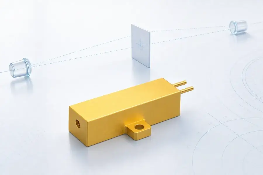
Diseñe el transmisor en torno al presupuesto de alcance requerido, no solo a la energía del pulso.
Lumexis desarrolla y fabrica fuentes láser compactas de Er:glass de 1535 nm para telemetría pulsada de tiempo de vuelo (ToF). La cartera abarca desde 40 a 500 µJ, 3–6 ns ancho de pulso y configuraciones desde 1–10 Hz hasta 1000 Hz, lo que brinda a los equipos de instrumentación un punto de partida práctico para telemetría compacta, medición asistida por cámara, instrumentos de campo, medición científica y subsistemas ópticos OEM.
A Fuente láser de 1535 nm para telemetría láser debe seleccionarse como una parte del enlace transmisor-receptor. Por lo tanto, esta página comienza con la adecuación a la aplicación y los parámetros exactos de la fuente, y luego conecta esos valores con las decisiones de óptica, sincronización, detección e integración.
Para seleccionar una fuente rápidamente, envíenos seis datos:
- material del objetivo, tamaño, ángulo y reflectividad esperada;
- distancia de trabajo normal y máxima;
- tasa de medición o actualización requerida;
- límites de apertura de transmisión y divergencia final del haz;
- límites de envolvente, masa, voltaje y temperatura de la fuente;
- apertura del receptor, tipo de detector y arquitectura de sincronización.
Ruta más rápida: Envíe su presupuesto de alcance y límites de integración para una recomendación de fuente.
Comience con la aplicación de telemetría
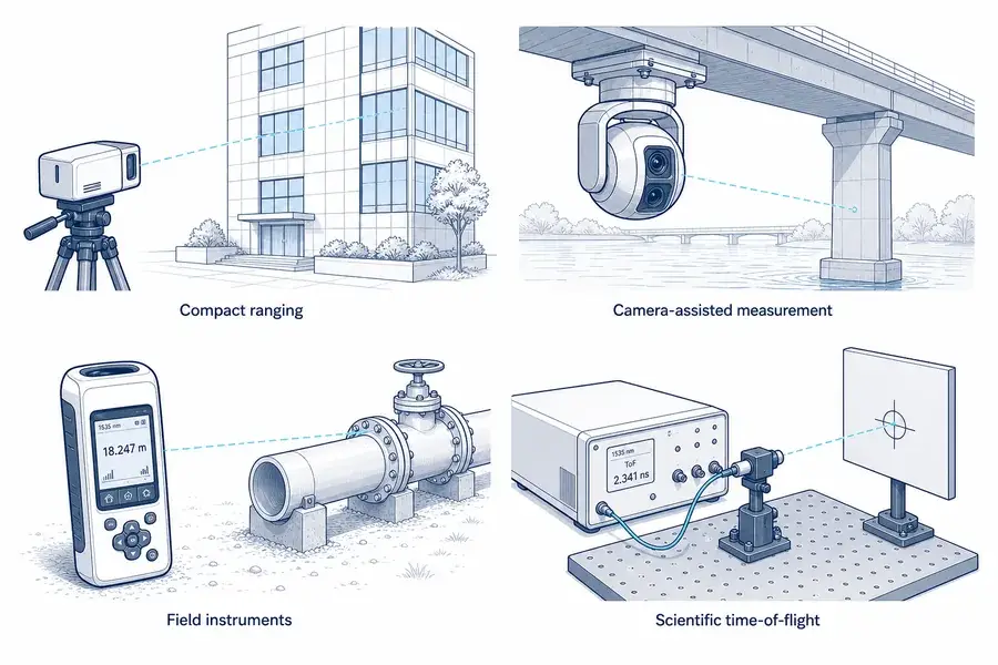
Adecuación a la aplicación
Adapte la fuente óptica a la tarea de medición real
Cuatro aplicaciones para fuentes láser de telemetría de 1535 nm: telemetría compacta, medición asistida por cámara, instrumentos de campo y sistemas científicos de tiempo de vuelo.
| Aplicación | Lo que aporta la fuente de 1535 nm | Lo que debe añadir el sistema final | Inicie la solicitud de cotización con |
|---|---|---|---|
| Telémetros ópticos compactos | Un pulso óptico corto para medición directa de ToF | controlador de fuente, óptica de transmisión, receptor, electrónica de sincronización, carcasa, interfaz | envolvente de distancia, objetivo, apertura, tasa, paquete |
| Medición civil asistida por cámara | Un canal de alcance a lo largo de una línea de visión calibrada | alineación cámara-láser, selección de objetivo, datos de pose o apuntado, procesamiento del host | campo de visión de la cámara, línea de mira, tamaño del objetivo, latencia |
| Instrumentos de mano y de campo | Emisión pulsada compacta para topografía, inspección de activos y mediciones científicas de campo | interfaz de usuario, gestión de energía, método de apuntado, receptor, calibración | tasa de actualización, temperatura de operación, presupuesto de batería, distancia más cercana |
| Instrumentos científicos de ToF | Un pulso nanosegundo controlado para experimentos de sincronización y mediciones remotas | definición de disparo, referencia de emisión, cadena de detección, adquisición de datos, análisis de incertidumbre | referencia de sincronización, tasa de repetición, ancho de banda del detector, registro |
| subsistemas ópticos OEM | Un bloque de construcción de fuente que puede empaquetarse en torno a óptica y electrónica específicas del proyecto | datum mecánico, ruta térmica, accionamiento eléctrico, aislamiento óptico, calificación | envolvente de volumen, montaje, voltaje, perfil de vida útil, plan de pruebas |
Qué es este producto y qué no es
La fuente láser de Er:glass es el emisor dentro de un transmisor de alcance. Crea el pulso óptico, pero por sí mismo no calcula la distancia ni proporciona un canal de medición de alcance completo.
Un telémetro funcional también requiere:
- un circuito de bombeo y excitación compatible;
- control de disparo y una referencia de tiempo de emisión definida;
- óptica de colimación o expansión del haz;
- una trayectoria hacia el objetivo y una ventana externa adecuada;
- óptica de recepción y filtrado espectral;
- un detector InGaAs y una cadena de receptor de bajo ruido;
- electrónica de temporización, detección, validación e interfaz con el host.
Esta distinción es importante en la adquisición. Una hoja de datos de la fuente debe compararse con otras fuentes. Un telémetro completo debe compararse por alcance condicionado al objetivo, alcance mínimo, precisión, comportamiento de medición válida, interfaz, empaque y rendimiento ambiental.
Haga coincidir la plataforma de fuente Lumexis
La tabla siguiente es una guía de selección inicial. Los valores son especificaciones nominales de la plataforma del producto; confirme el dibujo específico del pedido, las condiciones de operación y los criterios de aceptación antes de la liberación mecánica o eléctrica.
| Modelo | Longitud de onda | Energía de pulso | Tasa de repetición | Ancho de pulso | Divergencia de la fuente | Voltaje de alimentación | Temperatura de operación | Masa |
|---|---|---|---|---|---|---|---|---|
| 1535-LXER040 | 1535 nm | 40 µJ | 1000 Hz | 3–6 ns | ≤15 mrad | <2 V | −40 a +65 °C | Confirmar por configuración |
| 1535-LXER100 | 1535 nm | 100 µJ | 1–10 Hz | 3–6 ns | ≤10 mrad | <2 V | −40 a +65 °C | 9 g |
| 1535-LXER200 | 1535 nm | 200 µJ | 1–10 Hz | 3–6 ns | ≤10 mrad | <2 V | −40 a +65 °C | 9 g |
| 1535-LXER300 | 1535 nm | 300 µJ | 1–10 Hz | 3–6 ns | ≤10 mrad | <2 V | −40 a +65 °C | 9 g |
| 1535-LXER400 | 1535 nm | 400 µJ | 1–10 Hz | 3–6 ns | ≤15 mrad | <2 V | −40 a +65 °C | 11 g |
| 1535-LXER500 | 1535 nm | 500 µJ | 1–10 Hz | 3–6 ns | ≤15 mrad | <2 V | −40 a +65 °C | 13 g |
Lógica de selección práctica
Comience con 1535-LXER040 cuando la aplicación valora una alta tasa de repetición de la fuente y el sistema puede cerrar su presupuesto de alcance con pulsos de 40 µJ. A 1000 Hz, esta plataforma es adecuada para arquitecturas de muestreo de mayor tasa, experimentos de escaneo o sistemas que necesitan oportunidades más frecuentes para adquirir un retorno.
Comience con 1535-LXER100, 200 o 300 cuando el instrumento necesita más energía por pulso a una baja tasa de medición. Estas tres opciones comparten una clase de tasa de 1–10 Hz, ancho de pulso de 3–6 ns, divergencia de fuente ≤10 mrad y una masa listada de 9 g, lo que hace que la energía del pulso sea el primer diferenciador dentro de este grupo.
Considere 1535-LXER400 o 500 cuando el presupuesto del enlace necesita una clase de energía transmitida más alta y el paquete puede aceptar la fuente correspondiente de 11 g o 13 g. Una mayor energía puede agregar margen de retorno, pero no garantiza una distancia específica. La óptica de transmisión, el llenado del objetivo, la atmósfera, la apertura del receptor, el rendimiento del detector, el fondo y la lógica de detección siguen siendo parte del resultado.
No seleccione solo por la energía del pulso
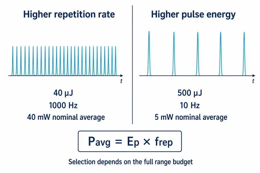
Dos fuentes pueden tener puntos de operación previstos muy diferentes incluso cuando ambas son adecuadas para la medición de alcance. La plataforma de 40 µJ proporciona una tasa de pulso mucho más alta; la plataforma de 500 µJ proporciona más energía en cada pulso pero a una tasa de repetición más baja. Esas elecciones afectan la oportunidad de muestreo, la señal máxima, la potencia óptica promedio, el comportamiento del excitador, el diseño térmico, la recuperación del detector y la validación a nivel del sistema.
Interacción de parámetros
Evalúe parámetros acoplados en el punto de operación
Comparación de una fuente de 40 µJ, 1000 Hz y una fuente de 500 µJ, 10 Hz, que ilustra las compensaciones entre tasa de repetición y energía del pulso.
Dónde encaja la fuente en un telémetro de tiempo de vuelo
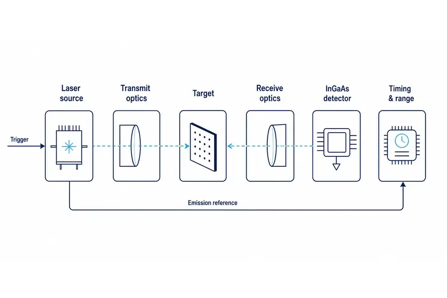
Arquitectura del sistema
Revise la cadena óptica y de medición completa
Arquitectura del sistema desde una fuente láser de 1535 nm a través de la óptica de transmisión, el objetivo, la óptica de recepción, el detector InGaAs y la electrónica de temporización.
Un instrumento de ToF directo mide el intervalo entre un pulso emitido y un retorno detectado. En la forma más simple, la distancia de un solo sentido es:
R = cΔt / 2
donde R es la distancia de un solo sentido, c es la velocidad de propagación de la luz, y Δ t es el intervalo de ida y vuelta medido. El factor de dos tiene en cuenta las trayectorias de salida y retorno. La explicación de altimetría láser de la NASA aplica la misma relación de ida y vuelta: la distancia de viaje óptico se calcula a partir de la velocidad de la luz y el tiempo transcurrido, y luego se divide por dos para el alcance de un solo sentido.1
La fuente participa en tres eventos de temporización:
- Comando o disparo: la electrónica de excitación inicia un ciclo de pulso.
- Emisión óptica: el pulso realmente sale de la fuente. Este evento puede no ser idéntico al borde del comando porque los retrasos del excitador y de acumulación pueden variar.
- Detección de retorno: el receptor identifica un retorno del objetivo y genera un evento de temporización.
Para una temporización de precisión, defina qué inicia el reloj. Un borde de comando es conveniente, pero un monitor de emisión o un retraso de emisión caracterizado puede proporcionar una mejor referencia. El enfoque correcto depende de la incertidumbre de alcance requerida, el diseño del excitador, el comportamiento de temperatura, el modo de repetición y la estrategia de calibración.
El receptor debe coincidir con la longitud de onda y el pulso
A 1535 nm, el receptor comúnmente usa un detector InGaAs en lugar de un detector de silicio. Los fotodiodos de avalancha InGaAs comerciales están disponibles con sensibilidad que cubre la región de 1.5 µm y se promocionan específicamente para aplicaciones de medición de distancia y receptor LiDAR.2
La elección del detector no es solo una decisión de longitud de onda. El equipo de ingeniería también debe definir:
- área activa y campo de visión óptico;
- responsividad o eficiencia de detección en la longitud de onda de operación;
- ganancia, ancho de banda, ruido y comportamiento de temperatura;
- saturación y recuperación después de retornos cercanos fuertes;
- filtrado de luz de fondo;
- umbral, fracción constante, correlación u otro método de temporización;
- Criterios de falsa alarma y detección válida.
Un pulso óptico más fuerte puede ayudar a la señal de retorno, pero también puede hacer que los objetivos cercanos, las reflexiones internas y la recuperación del receptor sean más exigentes. El transmisor y el receptor deben, por lo tanto, revisarse juntos.
Cómo leer los parámetros de la fuente
Energía de pulso: energía útil entregada en un evento
Energía de pulso E_p, expresada en microjulios, es la energía óptica en un solo pulso. En un sistema sin otros cambios, más energía transmitida puede aumentar la energía disponible para el retorno de un objetivo. En un instrumento real, “sin otros cambios” rara vez se cumple: el empaque, las condiciones de excitación, la tasa de repetición, la divergencia, la óptica, el rango dinámico del detector y la vida útil también pueden cambiar.
La energía de pulso no es una clasificación de distancia. El receptor solo ve una pequeña fracción del pulso emitido después de la dispersión del haz, la interacción con el objetivo, la pérdida atmosférica, la pérdida de recolección, el filtrado y la conversión del detector.
Ancho de pulso: una entrada de temporización a escala de nanosegundos
Las plataformas de fuente Lumexis Er:glass enumeran un rango de ancho de pulso de 3–6 ns. Los pulsos cortos apoyan la temporización directa de vuelo porque la forma de onda de retorno puede localizarse en el tiempo, pero el ancho de pulso es solo un contribuyente a la precisión de la distancia. El ancho de banda del detector, la relación señal-ruido, el umbral de temporización, la forma del pulso, la profundidad del objetivo, el método de muestreo y la calibración pueden ensanchar o desplazar el evento medido.
La longitud espacial aproximada de un pulso en espacio libre es cτ, pero el intervalo de alcance unidireccional correspondiente a una duración de ida y vuelta es cτ/2. Eso no significa que un pulso de 6 ns produce automáticamente una precisión fija de cτ/2. La electrónica de estimación puede localizar un evento dentro de una forma de onda, mientras que el ruido y la estructura del objetivo pueden mover el punto de temporización aparente. Use la precisión y repetibilidad medidas del sistema—no solo el ancho de pulso—para la aceptación.
Potencia máxima: una estimación que requiere una suposición de forma de pulso
Para una aproximación de pulso rectangular:
Ppico ≈ Ep / τp
Un pulso nominal de 100 µJ en 3–6 ns corresponde a una potencia promedio durante ese intervalo de pulso idealizado de aproximadamente 17–33 kW. Un pulso nominal de 500 µJ da aproximadamente 83–167 kW con la misma aritmética. Estas son estimaciones explicativas, no valores de producto garantizados: la potencia máxima real depende de la forma temporal medida del pulso y de la definición utilizada para el ancho de pulso.
La potencia máxima es importante para la formación de la señal de retorno y la revisión de componentes ópticos. No es lo mismo que la potencia óptica promedio, la potencia de entrada eléctrica o la demanda máxima de la fuente de alimentación del anfitrión.
Tasa de repetición: oportunidad de medición, no tasa de salida garantizada
La tasa de repetición describe con qué frecuencia la fuente puede emitir bajo el modo de operación especificado. Una tasa de pulso óptico de 1000 Hz puede soportar un muestreo frecuente, pero el instrumento terminado puede generar menos rangos válidos debido a la compuerta del receptor, la pérdida de objetivo, el procesamiento, el filtrado, la comunicación o la geometría de escaneo. Del mismo modo, una fuente de 10 Hz no garantiza diez valores de distancia aceptados por segundo.
Defina cuatro tasas separadas en la especificación del sistema:
- tasa de disparo comandada;
- tasa de emisión óptica confirmada;
- tasa de adquisición del receptor;
- tasa de salida de rango válido.
Mantener estos términos separados previene un error de integración común: tratar un número de repetición de la fuente como la tasa de datos garantizada del instrumento completo.
Potencia óptica promedio: energía de pulso multiplicada por la tasa
Para una fuente pulsada repetitiva:
Pavg = Epfrep
Esta relación explica por qué una fuente de menor energía y alta tasa puede tener más salida óptica promedio que una fuente de mayor energía y baja tasa. No proporciona la eficiencia eléctrica de la fuente ni la corriente máxima requerida de su controlador. Pregunte por separado sobre la entrada del controlador, el comportamiento de la corriente de pulso, el ciclo de trabajo, la secuencia de arranque y la ruta térmica.
Divergencia de la fuente: una entrada a la óptica de transmisión
El valor listado de ≤10 o ≤15 mrad describe la salida de la fuente, no necesariamente el haz final que sale del instrumento. Un telémetro completo normalmente añade óptica de colimación o expansión de haz para establecer el diámetro de salida, la divergencia, el frente de onda y el eje óptico.
Entrega óptica
Equilibre la potencia, la entrega del haz y la geometría del objetivo
Diagrama de integración óptica que muestra la divergencia de fuente bruta de 10–15 mrad, la óptica de colimación y el haz de transmisión final del sistema.
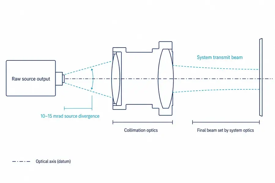
Para una estimación de campo lejano usando divergencia de ángulo completo:
d ≈ Rθ
donde d es el diámetro aproximado del haz en el objetivo, R es la distancia, y θ es la divergencia de ángulo completo en radianes. Esta relación simple es útil para el pensamiento de llenado del objetivo, pero el diámetro inicial del haz, el perfil del haz, el enfoque, la aberración, la turbulencia y el movimiento de apuntado también pueden importar.
Un haz final más estrecho puede colocar más energía en un objetivo pequeño y distante. También requiere un control más estricto de la línea de mira, el apuntado, la vibración y la deriva térmica. El eje de transmisión debe permanecer dentro del campo de visión del receptor y sobre el objetivo previsto durante toda la operación.
Por qué la longitud de onda sola no determina el rendimiento del sistema
La banda de 1535 nm es útil para fuentes pulsadas compactas de Er:glass y es compatible con la tecnología de receptores InGaAs establecida. También soporta un espacio de diseño de seguridad láser diferente de las longitudes de onda más cortas del infrarrojo cercano porque la absorción del tejido y los límites de exposición aplicables varían con la longitud de onda.
Sin embargo, ninguna etiqueta de longitud de onda establece la clasificación de un producto terminado. La clasificación depende de la emisión accesible, la energía de pulso, la duración del pulso, el patrón de repetición, la apertura, la divergencia, la geometría de exposición, el método de medición y el ensamblaje óptico completado. Lumexis definirá cualquier clasificación formal o declaración de cumplimiento solo para una configuración final documentada.
La longitud de onda tampoco elimina los límites ambientales. Niebla, lluvia, polvo, aerosoles, centelleo de calor, condensación y una ventana externa sucia pueden reducir el retorno utilizable o crear retrodispersión cercana no deseada. Pruebe el transmisor y receptor ensamblados a través de la ventana final en condiciones representativas.
El presupuesto de alcance: traduzca la aplicación en requisitos de fuente
Para un objetivo difuso, una relación direccional simplificada puede escribirse como:
psuperficie = psensor + Ruobservación
donde:
- E_r es la energía de pulso recibida;
- E_t es energía de pulso transmitida;
- ηtx y ηrx representan la eficiencia de la trayectoria de transmisión y recepción;
- T^2 representa la transmisión atmosférica bidireccional;
- Fobjetivo representa la fracción útil de la huella del haz sobre el objetivo;
- ρ es un término efectivo de retorno del objetivo para el modelo elegido;
- A_r es el área de apertura del receptor;
- R es el alcance.
Esta es una relación proporcional educativa, no una ecuación de aceptación universal. Los modelos exactos de enlace dependen de si el objetivo llena el haz, la geometría y dispersión del objetivo, el perfil del haz, el campo de visión del receptor, el fondo, las estadísticas de detección y la arquitectura del sistema. El análisis publicado de energía de retorno de ICESat/GLAS vincula igualmente la energía de pulso transmitida, el área del receptor, el alcance, la respuesta de la superficie y la transmisión atmosférica bidireccional.3
Ocho preguntas de presupuesto de alcance que mejoran una recomendación de fuente
¿Cuál es el objetivo?
Proporcione dimensiones, material, acabado, color solo como contexto de apoyo, reflectividad esperada a la longitud de onda de operación si se conoce, y el rango de ángulos de incidencia. Una pared difusa grande y un borde estrecho no son objetivos equivalentes.
¿Llena el objetivo la huella del haz?
Si la huella del haz sobrepasa el objetivo, solo parte de la energía transmitida interactúa de manera útil. Una fuente de mayor energía puede no compensar eficientemente un apuntamiento deficiente o un haz final sobredimensionado.
¿Cuál es el alcance normal, no solo el máximo?
La distancia de trabajo normal a menudo determina la mejor fuente. Un sistema diseñado solo en torno a un máximo extremo puede crear una señal de retorno cercano excesiva, tamaño innecesario, menor tasa, mayor costo o validación más difícil.
¿Qué atmósfera y ventana son realistas?
Especifique visibilidad, humedad, polvo, lluvia, niebla, altitud de operación, material de la ventana externa, recubrimientos, ángulo de incidencia y plan de contaminación. La pérdida se aplica en las trayectorias de salida y retorno.
¿Qué apertura de recepción está disponible?
Para una apertura circular, el área de recolección es A_r=π D^2/4. Aumentar el diámetro puede mejorar la recolección, pero también afecta la envolvente, la masa, el tamaño de la ventana, el campo de visión, la alineación y el costo.
¿Qué detector y umbral se utilizarán?
El ruido del receptor y el fondo establecen cuánto retorno se necesita para una probabilidad definida de detección y un nivel de falsa alarma. “Detectable” debe estar conectado a un criterio de aceptación.
¿Qué tan estable es la línea de visión?
Incluya error de apuntamiento, vibración, tolerancia mecánica, deriva de boresight, desplazamiento del eje óptico y cualquier error de alineación del escáner o cámara. Una divergencia más estrecha solo ayuda si el sistema ilumina consistentemente el objetivo previsto.
¿Qué comportamiento de medición válida se requiere?
Defina retornos perdidos, retornos falsos, escenas de múltiples superficies, lógica de primer/último/retorno más fuerte, gating, timeout y reporte de datos inválidos. La fuente crea pulsos; el sistema de medición completo decide qué retorno se convierte en una distancia.
Lista de verificación de integración para equipos de ingeniería OEM
Accionamiento eléctrico y disparo
- Confirme la configuración exacta de la fuente y el controlador compatible antes de aplicar energía.
- Defina los límites de suministro en los pines de la fuente bajo condiciones transitorias, no solo en la fuente de banco.
- Documente el nivel de disparo, flanco, duración del pulso, tasa permitida, comportamiento de inhibición y secuencia de arranque.
- Separe la referencia de emisión óptica del disparo de comando cuando el presupuesto de incertidumbre lo requiera.
- Revise la puesta a tierra, impedancia del cable, acoplamiento electromagnético y aislamiento del receptor en el gabinete completo.
Montaje mecánico
- Utilice el dato de montaje aprobado y los límites de sujetadores del plano específico del pedido.
- Evite la tensión del chasis que pueda alterar la alineación o dañar el paquete de la fuente.
- Defina la ubicación del eje óptico y la tolerancia angular relativa al dato del host.
- Reserve autoridad de ajuste o calibración si la pila de tolerancias de producción no puede mantener el boresight directamente.
- Verifique los requisitos de propiedades de masa y vibración en el instrumento ensamblado.
Tren óptico
- Seleccione la distancia focal del colimador, apertura libre, recubrimiento y distancia de trabajo para la salida real de la fuente.
- Verifique el recorte del haz a través de la tolerancia y la temperatura.
- Controle la retroalimentación y las reflexiones internas de lentes, filtros y la ventana externa.
- Mantenga la fuga de transmisión fuera del receptor o defina la recuperación y el gating en torno a ella.
- Mida la divergencia final y el alineamiento después del ensamblaje de la carcasa, no solo en el banco óptico.
Diseño térmico y ambiental
El rango de temperatura de operación de la plataforma es de −40 a +65 °C, pero el rendimiento del sistema terminado aún depende del driver, el montaje, la carcasa, la óptica, el detector y la calibración. Una fuente que opera dentro de los límites de temperatura no garantiza energía de pulso, temporización, alineación o alcance constantes para el instrumento completo.
Estructure el plan de calificación en torno a:
- arranque en frío y arranque en caliente;
- energía de pulso y retardo de emisión en función de la temperatura;
- perfiles de servicio de alta y baja frecuencia;
- deriva del eje óptico;
- condensación y contaminación de la ventana;
- vibración antes y después de la alineación;
- ruido del receptor y umbral de detección en función de la temperatura;
- ciclado repetido y límites de aceptación.
Producción y aceptación
Convierta la intención del sistema en mediciones que puedan repetirse:
- energía de pulso y método de medición;
- definición del ancho de pulso y ancho de banda del instrumento;
- longitud de onda central y método espectral;
- modo de repetición y perfil de servicio;
- definición de divergencia de la fuente y plano de medición;
- dato de referencia del eje óptico y error permitido;
- condiciones de prueba eléctrica;
- estado ambiental y tiempo de estabilización;
- trazabilidad, plan de muestreo y límites de aprobación/rechazo.
Cuanto más precisamente se definan estos elementos antes del lanzamiento del prototipo, más fácil será comparar muestras, controlar cambios de integración y escalar la producción.
Qué incluir en su RFQ
| Categoría | Información a proporcionar | Por qué Lumexis lo necesita |
|---|---|---|
| Aplicación | medición de distancia compacta, medición asistida por cámara, instrumento de campo, ToF científico o subsistema OEM | establece el patrón de operación y el límite de integración |
| Objetivo | tamaño, material, comportamiento de retorno, ángulo de incidencia, fondo | determina el retorno útil y el desafío de detección |
| Distancia | mínimo, normal, máximo y margen requerido | evita la selección en torno a un solo número destacado |
| Tasa | objetivos de disparo, emisión, adquisición y salida válida | separa la frecuencia de la fuente de la tasa de datos del sistema |
| Óptica de transmisión | apertura, divergencia final, diámetro del haz, ventana | conecta la divergencia de la fuente con el llenado del objetivo y la alineación |
| Receptor | apertura, campo de visión, dispositivo InGaAs, filtro, ancho de banda | completa el presupuesto de alcance |
| Sincronización | definición de disparo, referencia de emisión, precisión, latencia | define la cadena de medición de distancia |
| Mecánico | envolvente disponible, dato de referencia de montaje, límite de masa, eje óptico | identifica restricciones de empaquetado y alineación |
| Eléctrico | voltaje de la fuente, enfoque del driver, interfaz de control, ciclo de trabajo | admite la integración compatible de fuente y driver |
| Entorno | temperatura, vibración, humedad, contaminación, visibilidad | define las condiciones de validación |
| Calificación | cantidad de prototipos, plan de prueba, límites de aceptación, pronóstico de producción | alinea las muestras de desarrollo con un suministro escalable |
Preguntas frecuentes
¿Es una fuente láser de Er:vidrio de 1535 nm un telémetro láser completo?
No. Es el emisor pulsado utilizado en el transmisor. Un telémetro completo también necesita electrónica de excitación, óptica de transmisión, un receptor, detector, electrónica de temporización y detección, alineación mecánica, una trayectoria óptica externa y una interfaz de host.
¿Qué energía de pulso debería elegir para la medición de distancias largas?
Elija según un presupuesto de alcance, no solo por la distancia. Una mayor energía de pulso puede añadir margen al transmisor, pero el llenado del objetivo, la transmisión atmosférica, la apertura del receptor, la sensibilidad del detector, el fondo, el método de sincronización y la probabilidad de detección aceptable pueden ser igualmente decisivos. Envíe esos datos para obtener una recomendación significativa.
¿Es 40 µJ a 1000 Hz más débil que 500 µJ a 10 Hz?
No es una comparación útil de una sola palabra. La fuente de 500 µJ entrega más energía por pulso, lo que puede respaldar un retorno individual más fuerte. La fuente de 40 µJ emite con más frecuencia y tiene una salida óptica promedio nominal más alta a la tasa máxima indicada. La elección correcta depende de la tasa de adquisición, el retorno del objetivo, el comportamiento del detector, la potencia, el diseño térmico y el método de escaneo o muestreo.
¿La divergencia listada de 10–15 mrad equivale a la divergencia final del haz del telémetro?
No necesariamente. Es la especificación de salida de la fuente. El transmisor terminado normalmente utiliza óptica de colimación o expansión de haz para establecer el diámetro final del haz y la divergencia. El rendimiento final debe medirse después de que el ensamblaje óptico y mecánico esté alineado.
¿Puede el ancho de pulso convertirse directamente en precisión de distancia?
No. El ancho de pulso es parte del problema de temporización, pero la precisión también depende de la forma de onda, el detector y el ancho de banda electrónico, la relación señal-ruido, el umbral de temporización, la calibración, la profundidad del objetivo y las condiciones ambientales. Utilice la precisión medida del sistema bajo las condiciones de prueba indicadas.
¿Puede Lumexis personalizar la fuente para un instrumento OEM?
Lumexis puede revisar los requisitos específicos del proyecto para la salida óptica, el modo de repetición, la integración del paquete, el montaje, la compatibilidad del controlador, el uso ambiental, las pruebas y el suministro de producción. La viabilidad y las especificaciones finales se confirman mediante revisión de ingeniería.
¿Qué tecnología de receptor se utiliza comúnmente a 1535 nm?
Los fotodiodos de InGaAs y los fotodiodos de avalancha se utilizan ampliamente en la región de 1,5 µm. La selección del detector también debe tener en cuenta el área activa, la ganancia, el ancho de banda, el ruido, la luz de fondo, la temperatura, la saturación y el método de temporización.2
¿Qué datos se deben recopilar durante las pruebas de prototipos?
Registre la configuración de la fuente, la energía del pulso, el ancho del pulso, el modo de repetición, la referencia de emisión, el objetivo, la distancia, el ángulo del objetivo, la atmósfera, la óptica de transmisión, los ajustes del receptor, la temperatura, el comportamiento del suministro, el estado de detección bruto y la salida de rango válido. Esto hace que las fallas sean diagnosticables y las comparaciones repetibles.
Solicite una recomendación de fuente
Envíe a Lumexis su aplicación, objetivo, envolvente de distancia, tasa requerida, apertura de transmisión, divergencia final, concepto de receptor, límites de tamaño y masa, rango de temperatura, cantidad de prototipos y cronograma. Nuestros ingenieros ayudarán a asignar el proyecto a la plataforma de 40–500 µJ e identificarán las cuestiones ópticas, de temporización y de calificación que deben resolverse antes de la producción.
CTA sugerido: Solicite una recomendación de fuente láser de medición de distancia de 1535 nm.
CTA secundario: Comparta su presupuesto de alcance para revisión de ingeniería.
Lumexis: fuentes láser de precisión, diseñadas para el mundo real.
Referencias técnicas
Antecedentes técnicos adicionales consultados
- G. J. Spühler et al., “Experimentally confirmed design guidelines for passively Q-switched microchip lasers using semiconductor saturable absorbers,” proporciona antecedentes generales sobre la generación de pulsos; no documenta la construcción interna de los productos de Lumexis. Registro de artículo de Optica
- R. Häring et al., “Passively Q-switched microchip laser at 1.5 µm,” proporciona antecedentes revisados por pares sobre emisores pulsados compactos en esta región de longitud de onda; Lumexis no infiere una arquitectura idéntica a partir de esta fuente. Registro de artículo de Optica
Centro de Vuelo Espacial Goddard de la NASA, El Sistema Láser de Altimetría Geocientífica: Cómo la altimetría láser mide la distancia. Descripción técnica educativa ↩
Hamamatsu Photonics, APDs de InGaAs para medición de distancia y aplicaciones LiDAR. Descripción general de producto y técnica ↩↩
Investigación de NASA/ICESat, Mediciones de altimetría ICESat/GLAS: Rango dinámico de señal recibida y corrección de saturación. Artículo de acceso abierto ↩